Description
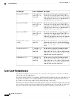
Chassis Slot Number
Line Card Type
Resides directly behind its corresponding packet
processing card. Each packet processing card can
support up to two FLC2s. The active card is installed
in the upper rear chassis slot. The redundant card is
installed in the lower rear chassis slot.
17 through 23, 26
through 39, or 42
through 48
Ethernet 10/100 (FLC2)
Resides directly behind its corresponding packet
processing card. Each packet processing card can
support up to two GLC2s. The active card is installed
in the upper rear chassis slot. The redundant card is
installed in the lower rear chassis slot.
17 through 23, 26
through 39, or 42
through 48
Ethernet 1000 (GLC2)
Resides directly behind its corresponding packet
processing card. Each packet processing card can
support up to two QGLCs. The active card is
installed in the upper rear chassis slot. The redundant
card is installed in the lower rear chassis slot.
17 through 23, 26
through 39, or 42
through 48
Quad Gig-E (QGLC)
Resides directly behind its corresponding packet
processing card. The XGLC is a full-height line card
that occupies the upper and lower slots in the ASR
5000.
17 through 23 and 26
through 32
10 Gigabit Ethernet Card
(XGLC)
Resides directly behind its corresponding packet
processing card. Each packet processing card can
support up to two OLC2s. The active card is installed
in the upper rear chassis slot. The redundant card is
installed in the lower rear chassis slot.
17 through 23, 26
through 39, or 42
through 48
Optical (ATM) (OLC2)
Resides directly behind its corresponding packet
processing card. Each packet processing card can
support up to two CLC2s. The active card is installed
in the upper rear chassis slot. The redundant card is
installed in the lower rear chassis slot.
7 through 23, 26
through 39, or 42
through 48
Channelized (CLC2)
Line Card Redundancy
To optimize network efficiency and minimize down time, the system supports 1:1 redundancy for OLC2s,
CLC2s, FLC2s, GLC2s, and QGLCs.
With the exception of the XGLC, line cards are installed in the half-height slots at the rear of the chassis. This
design allows two Ethernet or two Optical (ATM) or two Channelized line cards directly behind (one top,
one bottom) every packet processing card that normally operates in active mode.
When two line cards are installed, the card in the upper-rear chassis slot is automatically the active card. The
card in the lower-rear chassis slot is automatically placed in standby mode. In the event that the active card
experiences a failure, the system automatically migrates traffic to the standby card in the lower slot.
ASR 5000 Installation Guide
76
Line Card Installation
Line Card Redundancy
Summary of Contents for ASR 5000
Page 16: ...ASR 5000 Installation Guide xvi About this Guide Contacting Customer Support ...
Page 64: ...ASR 5000 Installation Guide 48 Installation Procedure Overview Laser Notice ...
Page 100: ...ASR 5000 Installation Guide 84 Line Card Installation Installing the XGLC ...
Page 122: ...ASR 5000 Installation Guide 106 Cabling the Fast Ethernet 10 100 Line Card FLC2 Interfaces ...
Page 206: ...ASR 5000 Installation Guide 190 Removing and Installing SMC PC Cards Removing PC Cards ...
Page 212: ...ASR 5000 Installation Guide 196 Replacing the Chassis Air Filter Installing the Air Filter ...
Page 220: ...ASR 5000 Installation Guide 204 Replacing a Power Filter Unit What to do with the Failed PFU ...
Page 266: ...ASR 5000 Installation Guide 250 Safety Electrical and EMC Certifications Korean EMC ...
Page 270: ...ASR 5000 Installation Guide 254 Environmental Specifications Chassis Air Flow ...

