Step 2
Verify that your port configuration settings are correct by entering the following command:
[
context_name
]
host_name
#
show configuration port slot#/port#
slot#
is the chassis slot number of the line card on which the physical port resides.
slot#
can be any integer value from
17 to 39, and 42 to 48.
This command produces an output similar to that displayed in the following example that shows the configuration for
port 1 on the line card installed in chassis slot 17.
In this example, the port is bound to an interface called
rp1
configured in a context called
source
.
config
port ethernet 17/1
description LC17/1_RP1
no shutdown
bind interface rp1 source
#end
Step 3
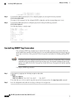
Verify that your static route(s) was configured properly by entering the following command:
[
context_name
]
host_name
#
show ip static-route
This command produces an output similar to that displayed in the following example that shows a static route to a gateway
with an IP address of 192.168.250.1.
Destination
Nexthop
Protocol
Prec
Cost
Interface
0.0.0.0/0
192.168.250.1
Static
0
0
SPIO1
0.0.0.0/0
192.168.250.1
Static
0
0
rp1 source
Step 4
Save the configuration as described in the
Verifying and Saving Your Configuration
chapter.
ATM Interfaces and Ports
This section describes the minimum configuration required to use IP over ATM (IPoA) through an Optical
ATM line card (OLC/OLC2). The procedures describe how to:
Step 1
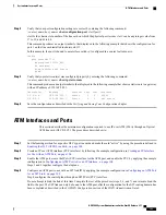
Set the framing method for a specific OLC-type line card and make the card "active" by using the procedure defined in
Enabling the OLC (ATM) Line Card, on page 104
.
Step 2
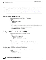
Create an IP over ATM interface (PVC interface) by following the example configuration in
for Use with an ATM Port, on page 104
.
Step 3
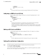
Enable the ATM port, create the IPoA (PVC) interface for the ATM port, and enable the PVC by applying the example
configuration in
Configuring an ATM Port to Use an IP Interface, on page 104
.
Steps 2 and 3 together configure the data plane.
Step 4
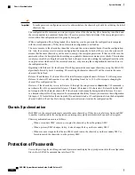
Configure an ATM port to use with an SS7 link ID by applying the example configuration in
for an SS7 Link, on page 105
.
Step 4 configures the control plane through an SS7/IPoA (PVC) interface.
Do not attempt to bind the link at this time. Complete the rest of the procedure (steps 5, 6, and 7) and return to bind the
link to the port. The SS7 link can only be bound to the ATM port after the configuration for the SS7 routing domain has
been completed as described in the
3G SGSN Configuration
section of the
SGSN Administration Guide
.
ASR 5000 System Administration Guide, StarOS Release 21.1
103
System Interfaces and Ports
ATM Interfaces and Ports
Summary of Contents for ASR 5000
Page 26: ...ASR 5000 System Administration Guide StarOS Release 21 1 xxvi Contents ...
Page 316: ...ASR 5000 System Administration Guide StarOS Release 21 1 288 VLANs VLAN Related CLI Commands ...
Page 400: ...ASR 5000 System Administration Guide StarOS Release 21 1 372 Engineering Rules ECMP Groups ...


