Step 7
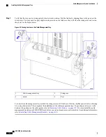
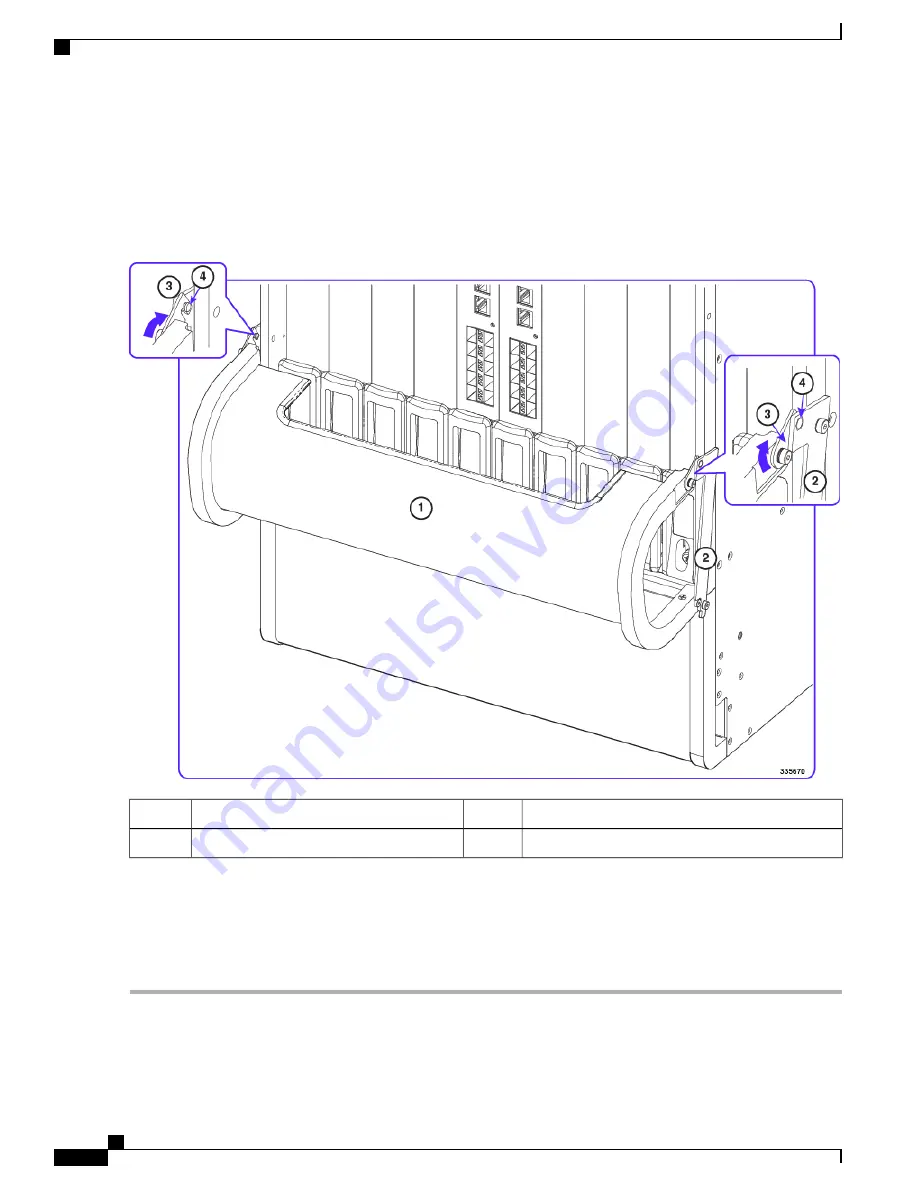
Verify that the tray can be swung upward into its closed position. Test the latches by clipping them to the posts on the
swing arms. You may need to apply slight inward pressure on the latches so they will clear the swing arms and rest on
the posts. See the figure below.
Figure 33: Testing Latches on the Cable Management Tray
Swing arm
2
Cable management tray
1
Post
4
Latch
3
To lower the cable management tray, unlatch the swing arms and lift the base of the tray slightly upward before allowing
it to swing downwards. This completes the installation of the cable management tray. To gain improved access to the
hook-and-loop straps on the cable guides, refer to
Removing Cable Guides, on page 159
. You must install the cable
management bracket on each MIO/UMIO card before you can route and secure network cables. For additional information,
refer to
Installing Cable Management Brackets, on page 160
.
ASR 5500 Installation Guide
158
Cable Management System Installation
Installing the Cable Management Tray
Summary of Contents for ASR 5500
Page 12: ...ASR 5500 Installation Guide xii Contents ...
Page 16: ...ASR 5500 Installation Guide xvi About this Guide Contacting Customer Support ...
Page 40: ...ASR 5500 Installation Guide 24 Technical Specifications Chassis Grounding ...
Page 74: ...ASR 5500 Installation Guide 58 Card Installation Save Shipping Cartons ...
Page 88: ...ASR 5500 Installation Guide 72 MIO Port Cabling Cleaning Fiber Optic Connectors ...
Page 112: ...ASR 5500 Installation Guide 96 System Power up show leds Command ...
Page 130: ...ASR 5500 Installation Guide 114 Initial System Configuration Additional Configuration Tasks ...
Page 164: ...ASR 5500 Installation Guide 148 Replaceable Components Returning Failed Components ...
Page 186: ...ASR 5500 Installation Guide 170 Console Port to Cisco Server Cabling Configuration ...
Page 192: ...ASR 5500 Installation Guide 176 RMA Shipping Procedures Rear Cards ...


