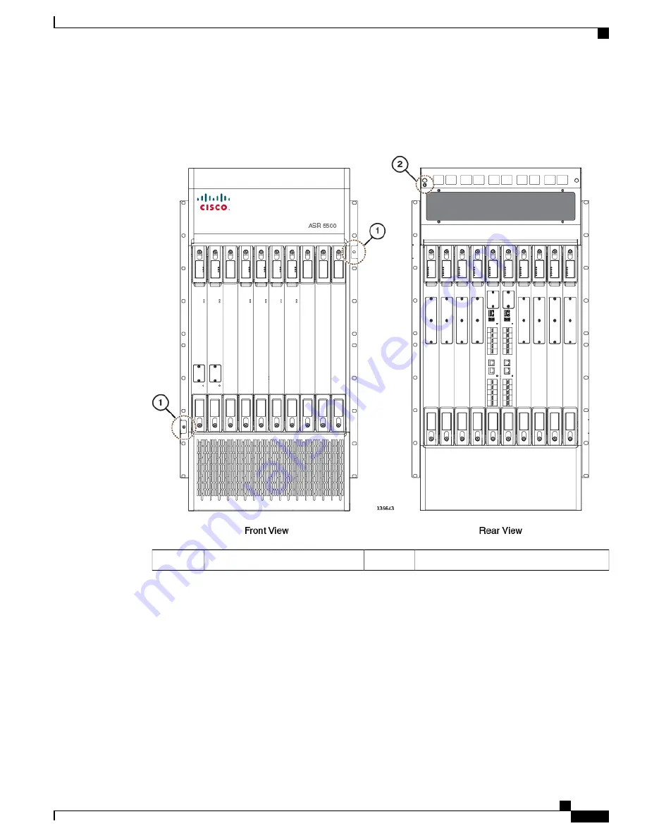
Before the you can use the ESD jacks on the ASR 5500 chassis and its mounting brackets, you must first
connect the chassis to ground according to the instructions in the
Chassis Installation
chapter of this document.
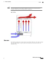
Figure 9: Locations of ESD Jacks on the ASR 5500 Chassis
Rear ESD jack
2
Front ESD jack
1
Standards Compliance
FCC Warning
This device complies with the limits for a Class A digital device, pursuant to Part 15 of the FCC Rules and
Regulations. Operation is subject to the following two conditions:
•
This device may not cause harmful interference.
ASR 5500 Installation Guide
29
Installation Procedure Overview
Standards Compliance
Summary of Contents for ASR 5500
Page 12: ...ASR 5500 Installation Guide xii Contents ...
Page 16: ...ASR 5500 Installation Guide xvi About this Guide Contacting Customer Support ...
Page 40: ...ASR 5500 Installation Guide 24 Technical Specifications Chassis Grounding ...
Page 74: ...ASR 5500 Installation Guide 58 Card Installation Save Shipping Cartons ...
Page 88: ...ASR 5500 Installation Guide 72 MIO Port Cabling Cleaning Fiber Optic Connectors ...
Page 112: ...ASR 5500 Installation Guide 96 System Power up show leds Command ...
Page 130: ...ASR 5500 Installation Guide 114 Initial System Configuration Additional Configuration Tasks ...
Page 164: ...ASR 5500 Installation Guide 148 Replaceable Components Returning Failed Components ...
Page 186: ...ASR 5500 Installation Guide 170 Console Port to Cisco Server Cabling Configuration ...
Page 192: ...ASR 5500 Installation Guide 176 RMA Shipping Procedures Rear Cards ...


