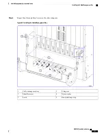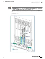
Cable management tray
2
Cable management bracket
1
Cable guides
3
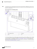
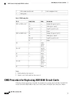
Table 27: CMS Routing Paths
Destination
Notes
Cable Guide
Card
Bottom DC (ports 20 to 29)
—
3A
MIO or UMIO, slot 5
1GbE (ports 1 and 2)
—
3A
Top DC (ports 10 to 19)
1
3B or 3C
Future
2
3C
Bottom DC (ports 20 to 29)
—
3D
MIO or UMIO, slot 6
1GbE (ports 1 and 2)
—
3D
Top DC (ports 10 to 19)
1
3E or 3F
Future
2
3F
1GbE
(ports 1
and 2)
—
3D
Top DC
(ports 10
to 13)
1
3E or 3F
Future
2
3F
1GbE
(ports 1
and 2)
—
3D
Top DC
(ports 10
to 13)
1
3E or 3F
Future
2
3F
Notes:
1
If cable guide has been removed.
2
Already in use if cable guide has been removed.
CMS Procedure for Replacing ASR 5500 Circuit Cards
When the cable management tray is installed, the procedure for removing circuit cards from the ASR 5500
chassis varies from that described in the
Circuit Cards
section of the
Replaceable Components
chapter.
ASR 5500 Installation Guide
164
Cable Management System Installation
CMS Procedure for Replacing ASR 5500 Circuit Cards
Summary of Contents for ASR 5500
Page 12: ...ASR 5500 Installation Guide xii Contents ...
Page 16: ...ASR 5500 Installation Guide xvi About this Guide Contacting Customer Support ...
Page 40: ...ASR 5500 Installation Guide 24 Technical Specifications Chassis Grounding ...
Page 74: ...ASR 5500 Installation Guide 58 Card Installation Save Shipping Cartons ...
Page 88: ...ASR 5500 Installation Guide 72 MIO Port Cabling Cleaning Fiber Optic Connectors ...
Page 112: ...ASR 5500 Installation Guide 96 System Power up show leds Command ...
Page 130: ...ASR 5500 Installation Guide 114 Initial System Configuration Additional Configuration Tasks ...
Page 164: ...ASR 5500 Installation Guide 148 Replaceable Components Returning Failed Components ...
Page 186: ...ASR 5500 Installation Guide 170 Console Port to Cisco Server Cabling Configuration ...
Page 192: ...ASR 5500 Installation Guide 176 RMA Shipping Procedures Rear Cards ...


