background image

the server is in standalone mode, further DHCP requests from the Cisco card are disabled. Use the Cisco Card
NIC mode if you want to connect to Cisco IMC through a Cisco card in standalone mode.

Shared LOM

—The 1-Gb/10-Gb Ethernet ports are used to access Cisco IMC. You must select either the

Active-Active

or

Active-standby

NIC redundancy setting in the following step.

Dedicated

—The dedicated management port is used to access Cisco IMC. You must select the

None

NIC redundancy

setting in the following step.

Cisco Card

—The ports on an installed Cisco UCS Virtual Interface Card (VIC) are used to access the Cisco IMC.

You must select either the

Active-Active

or

Active-standby

NIC redundancy setting in the following step.

See also the required VIC Slot setting below.
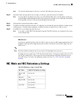
Step 2

Set the NIC redundancy to your preference. This server has three possible NIC redundancy settings:

None

—The Ethernet ports operate independently and do not fail over if there is a problem. This setting can be

used only with the Dedicated NIC mode.

Active-standby

—If an active Ethernet port fails, traffic fails over to a standby port. Shared LOM and Cisco Card

modes can each use either Active-standby or Active-active settings.

Active-active

(default)—All Ethernet ports are utilized simultaneously. The Shared LOM EXT mode must use

only this NIC redundancy setting. Shared LOM and Cisco Card modes can each use either Active-standby or
Active-active settings.

Step 3

Choose whether to enable DHCP for dynamic network settings, or to enter static network settings.

Before you enable DHCP, you must preconfigure your DHCP server with the range of MAC addresses for
this server. The MAC address is printed on a label on the rear of the server. This server has a range of six
MAC addresses assigned to Cisco IMC. The MAC address printed on the label is the beginning of the range
of six contiguous MAC addresses.

Note

The

static

IPv4 and IPv6 settings include the following:

• The Cisco IMC IP address.

For IPv6, valid values are 1 - 127.

• The gateway.

For IPv6, if you do not know the gateway, you can set it as none by entering :: (two colons).

• The preferred DNS server address.

For IPv6, you can set this as none by entering :: (two colons).

Step 4

(Optional) Make VLAN settings.

Step 5

Press

F1

to go to the second settings window, then continue with the next step.

From the second window, you can press

F2

to switch back to the first window.

Step 6

(Optional) Set a hostname for the server.

Step 7

(Optional) Enable dynamic DNS and set a dynamic DNS (DDNS) domain.

Step 8

(Optional) If you check the Factory Default check box, the server reverts to the factory defaults.

Step 9

(Optional) Set a default user password.

Installing the Server

14

Installing the Server

Setting Up the System With the Cisco IMC Configuration Utility

Summary of Contents for C480M5

Page 1: ...for important safety information Note IMPORTANT SAFETY INSTRUCTIONS This warning symbol means danger You are in a situation that could cause bodily injury Before you work on any equipment be aware of the hazards involved with electrical circuitry and be familiar with standard practices for preventing accidents Use the statement number provided at the end of each warning to locate its translation i...

Page 2: ...Statement 1017 Warning This equipment must be grounded Never defeat the ground conductor or operate the equipment in the absence of a suitably installed ground conductor Contact the appropriate electrical inspection authority or an electrician if you are uncertain that suitable grounding is available Statement 1024 Warning For Nordic countries Norway Finland Sweden and Denmark this system must be ...

Page 3: ...following guidelines Plan your site configuration and prepare the site before installing the server See the Cisco UCS Site Preparation Guide for the recommended site planning tasks Ensure that there is adequate space around the server to allow for accessing the server and for adequate airflow The airflow in this server is from front to back Ensure that the air conditioning meets the thermal requir...

Page 4: ...cautions to ensure that the system remains stable The following guidelines are provided to ensure your safety This unit should be mounted at the bottom of the rack if it is the only unit in the rack When mounting this unit in a partially filled rack load the rack from the bottom to the top with the heaviest component at the bottom of the rack If the rack is provided with stabilizing devices instal...

Page 5: ... L for left or R for right Note a Align the left inner rail marked L with the left side of the chassis as viewed from the front Align the 10 keyed slots in the rail with the 10 pegs on the side of the chassis b Set the keyed slots over the pegs and then slide the rail toward the front to lock it in place on the pegs c Install the right inner rail marked R to the right side of the chassis as viewed...

Page 6: ...rack unit b Push the front mounting pegs into the rack post holes until you hear them click and lock c Adjust the slide rail length until it reaches the rear rack post perfectly level Ensure that the rail is perfectly level and that the same height rack post holes are used in the front and rear posts Note d Hold open the rear peg spring latch then push the rear mounting pegs into the rear rack pos...

Page 7: ...e Caution The rack rail channels are fragile to side loads Install the chassis gently to avoid damaging the rails Note a Align the rear ends of the inner rails that are attached to the server sides with the front ends of the empty intermediate rails on the rack Ensure that the inner rails on the chassis are parallel with the intermediate rails on the rack This could require adjusting the mechanica...

Page 8: ...the rack with servers installed With the server fully pushed into the slide rails open a hinged slam latch lever on the front of the server and insert a screw through the hole that is under the lever The screw threads into the static part of the rail on the rack post and prevents the server from being pulled out Repeat for the opposite slam latch Depressing the release clips on the inner rails all...

Page 9: ... tab on arm farthest from server attaches to end of stationary outer slide rail 1 Rear of server 4 CMA tab on arm closest to the server attaches to end of inner slide rail attached to server 2 Step 2 Slide the CMA tab that is closest to the server over the end of the inner rail that is attached to the server Slide the tab over the end of the rail until it clicks and locks Step 3 Pull out the width...

Page 10: ...der Depress and hold the metal button on the outside of the tab and pivot the tab 180 degrees so that it points toward the rear of the server Figure 6 Reversing the CMA Metal button on outside of tab 2 CMA tab on end of width adjustment slider 1 Initial Server Setup This section describes how to power on the server assign an IP address and connect to server management when using the server in stan...

Page 11: ...tup through your dedicated management LAN To configure the system remotely you must have a DHCP server on the same network as the system Your DHCP server must be preconfigured with the range of MAC addresses for this server node This server node has a range of six MAC addresses assigned to the Cisco IMC The MAC address printed on the label is the beginning of the range of six contiguous MAC addres...

Page 12: ... z Base 10 digits 0 through 9 Non alphabetic characters _ Step 4 Continue with Setting Up the System With the Cisco IMC Configuration Utility on page 13 Connecting to the Server Remotely For Setup This procedure requires the following equipment One RJ 45 Ethernet cable that is connected to your management LAN Before you begin To configure the system remotely you must have a DHCP server on the same...

Page 13: ...r Strong Password The password can have minimum 8 characters maximum 14 characters The password must not contain the user s name The password must contain characters from three of the following four categories English uppercase letters A through Z English lowercase letters a through z Base 10 digits 0 through 9 Non alphabetic characters _ Step 9 Continue with Setting Up the System With the Cisco I...

Page 14: ...ared LOM EXT mode must use only this NIC redundancy setting Shared LOM and Cisco Card modes can each use either Active standby or Active active settings Step 3 Choose whether to enable DHCP for dynamic network settings or to enter static network settings Before you enable DHCP you must preconfigure your DHCP server with the range of MAC addresses for this server The MAC address is printed on a lab...

Page 15: ...ly assigned IP and MAC addresses are displayed on the console screen during bootup Note What to do next Use a browser and the IP address of the Cisco IMC to connect to the Cisco IMC management interface The IP address is based upon the settings that you made either a static address or the address assigned by your DHCP server The factory default username for the server is admin The default password...

Page 16: ...n the following step See also the required VIC Slot setting below This server has the following NIC redundancy settings that you can choose from None The Ethernet ports operate independently and do not fail over if there is a problem This setting can be used only with the Dedicated NIC mode Active standby If an active Ethernet port fails traffic fails over to a standby port Shared LOM and Cisco Ca...

Page 17: ...pdating the firmware Recommended method for firmware update Use the Cisco Host Upgrade Utility to simultaneously upgrade the Cisco IMC BIOS and component firmware to compatible levels See the Cisco Host Upgrade Utility Quick Reference Guide for your firmware release at the documentation roadmap link below You can upgrade the Cisco IMC and BIOS firmware by using the Cisco IMC GUI interface See the ...

Page 18: ...Installing the Server 18 Installing the Server Updating the BIOS and Cisco IMC Firmware ...

Reviews: