1-10
Cisco 1900 Series Hardware Installation
OL-19084-02
Chapter 1 Overview of the Router
Hardware Features
Table 1-3
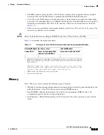
summarizes the memory options for Cisco 1900 series routers. The default memory numbers
for RAM represent the minimum usable memory. You can install additional RAM in multiples of the
default amount, up to the maximum amount on the Cisco 1940 series ISRs. The Cisco 1905 and Cisco
1921 have factory installed, fixed memory modules and no expansion slots.
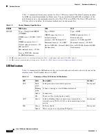
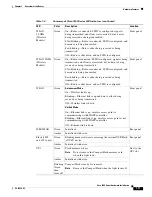
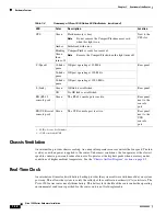
LED Indicators
Table 1-4
summarizes the LED indicators that are located in the router bezel or chassis, but not on the
interface cards. Not all models have every LED.
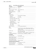
Table 1-3
Router Memory Specifications
DRAM
1940 Series
1905
1921
DRAM
Type—Unregistered DIMM
(UDIMM)
DIMM sizes—512 MB, 1 GB, 2
GB
DIMM expansion slots—1
Default onboard memory—512
MB non ECC
Maximum memory—2.5 GB
Boot or NVRAM—Internal
16-MB flash memory.
Type—DDR2
DIMM expansion slots—0
Default onboard
memory—256
1
MB non ECC
Maximum memory—512 MB
2
Boot or NVRAM—Internal 16 MB
flash memory.
1.
256 MB cannot support net boot or warm upgrade functions. Net boot and warm upgrade require 512 MB of memory.
2.
512 MB activation requires memory licensing feature. See the
Cisco IOS Software Activation Configuration Guide
for details.
Type—DDR2
DIMM expansion slots—0
Default onboard
memory—512 MB non ECC
Maximum memory—512 MB
Boot or NVRAM—Internal 16 MB
flash memory.
Table 1-4
Summary of Cisco 1900 Series LED Indicators
LED
Color
Description
Location
SYS
Solid
green
Solid green indicates normal operation.
Front panel
Blinking
green
System is booting or is in ROM monitor mode.
Amber
System error.
Off
Power is off or system board is faulty.
ACT
Green
Solid or blinking when any packets are transmitted or
received on any WAN or LAN, or when monitoring system
activity.
Front panel
PoE
Green
PoE is available.
Front panel
Amber
Power supply is not supplying PoE power.


