4-11
Cisco 1900 Series Hardware Installation
OL-19084-02
Chapter 4 Installing and Connecting the Router
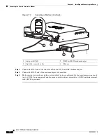
Installing the Chassis Ground Connection
Step 3
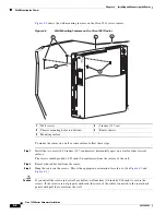
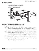
Attach the ring terminal to the chassis. The attachment points for the Cisco 1941 router are shown in
Figure 4-11
. Use a number 2 Phillips screwdriver and the screw supplied with the ground lug. Tighten
the screw to a torque of 8 to 10 in-lb. (0.9 to 1.1 N-m).
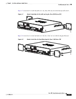
Figure 4-10
Chassis Ground Connection on the Cisco 1905 and Cisco 1921 Routers
Figure 4-11
Chassis Ground Connection on the Cisco 1941 Router
Step 4
Connect the other end of the ground wire to a known good electrical ground point. Please consult with
a licensed electrician if you have any questions about the suitability of the ground connection.
After the router is installed and properly grounded, you can connect the WAN and LAN cables as
required for your installation. For cable connection procedures, see the
“Cable Connection Procedures
for Cisco 1900 Series Routers”
chapter.
S
L
CONSOLE
AUX
GE 0/0
GE 0/1
POE
Cisco
1905
RESET
S
L
BAUD
48VDC 1.67A
100-240
V~ 50-60 Hz 1A
253714
GE 0/1
CONSOLE
EN
EN
L
S
USB
1
G
E
0
/
0
0
251359


