background image


3-6

Catalyst 2350 Switch Hardware Installation Guide

OL18479-01

Chapter 3      Power Supply and Fan Module Installation

Installing a DC-Power Supply

Step 6

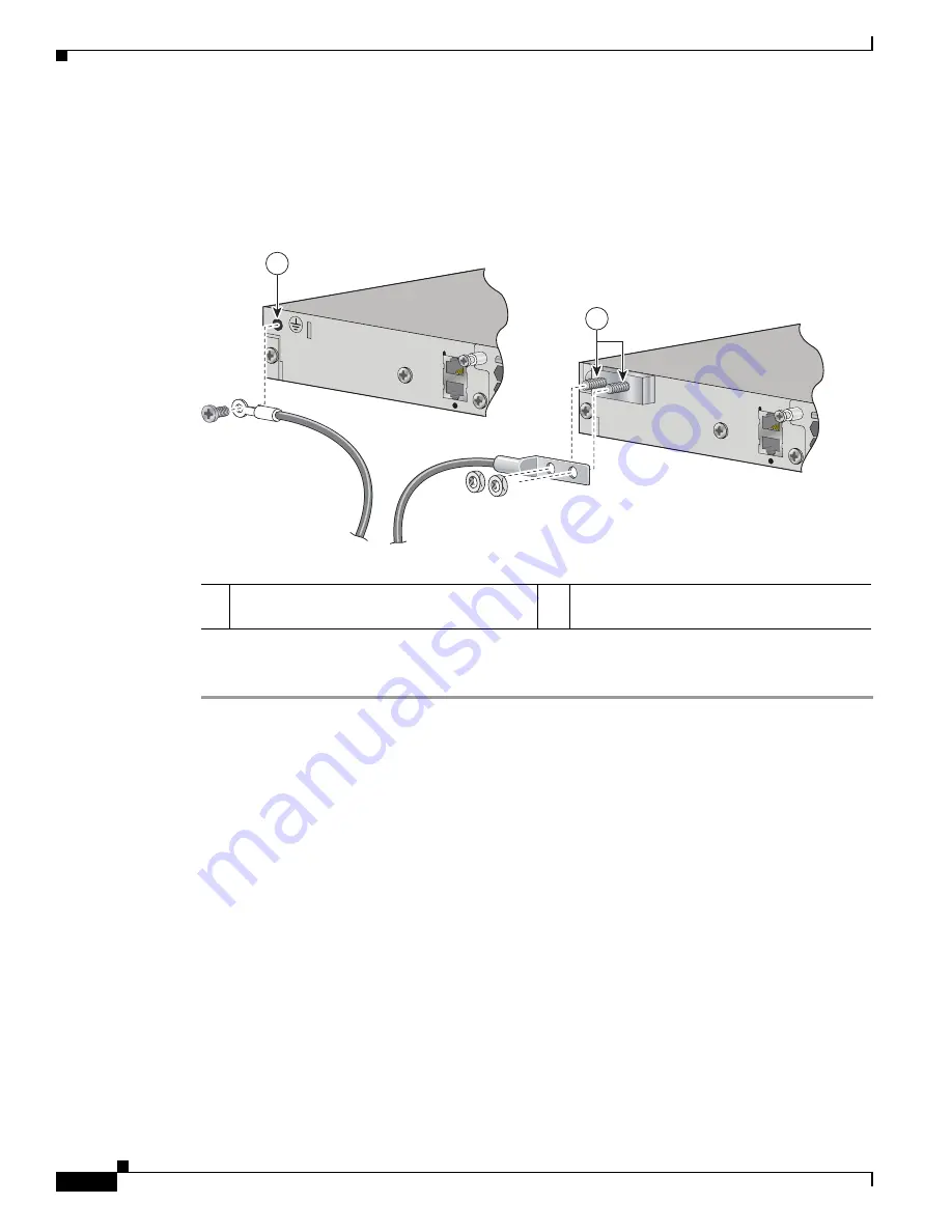
Using a ratcheting torque screwdriver, torque the ground-lug screws to 60 lbf-in (960 ozf-in) 
(

Figure 3-5

).

Step 7

Connect the other end of the grounding wire to an appropriate grounding point at your site or to the rack.

Figure 3-5

Attaching the Ground Lug and Wire Assembly on Catalyst 2350 Switches

Installing the DC Power Supply in the Switch

Step 1

Turn off power at the DC circuits. Locate the circuit breakers for the DC circuits, switch the circuit 
breakers to the OFF position, and tape the circuit-breaker switches in the OFF position.

Step 2

Use a number-2 Phillips screwdriver to remove the plastic safety cover from the power supply terminal 
blocks.

Step 3

Use a number-1 Phillips screwdriver to remove the DC-input power wires from the power terminals.

Step 4

Use a Phillips screwdriver to loosen the two captive screws at the lower edge of the module that secure 
it to the switch chassis.

Step 5

Remove the power-supply module from the power slot by pulling on the extraction handle.

Step 6

Insert the new power supply into the power-supply slot, and gently push it in (

Figure 3-6

). When 

correctly inserted, the power supply is flush with the switch rear panel.

1

Single-ground screw and lug ring.


Used with AC power supply.

2

Dual-ground adaptor and dual-hole lug.


Used with DC power supply.

273901

1

2

Summary of Contents for Catalyst 2350

Page 1: ...co Systems Inc 170 West Tasman Drive San Jose CA 95134 1706 USA http www cisco com Tel 408 526 4000 800 553 NETS 6387 Fax 408 527 0883 Catalyst 2350 Switch Hardware Installation Guide February 2009 Text Part Number OL 18479 01 ...

Page 2: ...radio antenna until the interference stops Move the equipment to one side or the other of the television or radio Move the equipment farther away from the television or radio Plug the equipment into an outlet that is on a different circuit from the television or radio That is make certain the equipment and the television or radio are on circuits controlled by different circuit breakers or fuses Mo...

Page 3: ...000 Ethernet Ports 1 2 10 Gigabit Ethernet Module Slots 1 2 Cisco TwinGig Converter Module 1 2 SFP Modules 1 3 LEDs 1 3 System LED 1 4 Port LEDs and Modes 1 4 Rear Panel Description 1 5 Power Supply Modules 1 5 Catalyst 2350 Switch Power Supply Modules 1 6 Fan Modules 1 6 Management Ports 1 7 Management Options 1 8 Network Configurations 1 8 C H A P T E R 2 Switch Installation 2 1 Preparing for In...

Page 4: ...ices to the Ethernet Ports 2 16 10 100 1000 Ethernet Port Connections 2 16 Where to Go Next 2 17 C H A P T E R 3 Power Supply and Fan Module Installation 3 1 Installation Overview 3 1 Tools and Equipment 3 1 Installation Guidelines 3 1 Installing an AC Power Supply 3 3 Installing a DC Power Supply 3 4 Preparing for Installation 3 4 Grounding the Switch 3 5 Installing the DC Power Supply in the Swi...

Page 5: ...et Module Interfaces B 2 SFP Modules B 2 10 100 Ethernet Management Port B 3 Console Port B 4 Cable and Adapter Specifications B 4 10 Gigabit Ethernet X2 Transceiver Module Cable Specifications B 4 SFP Module Cable Specifications B 5 Four Twisted Pair Cable Pinouts B 5 Two Twisted Pair Cable Pinouts B 6 Identifying a Crossover Cable B 6 Console Port Adapter Pinouts B 7 A P P E N D I X C Configurin...

Page 6: ...Contents vi Catalyst 2350 Switch Hardware Installation Guide OL18479 01 ...

Page 7: ... to configure your switch For more information see the switch getting started guide the switch software configuration guide the switch command reference and the switch system message guide on the Cisco com Technical Support and Documentation home page For information about the standard Cisco IOS Release 12 1 or 12 2 commands see the Cisco IOS documentation set from the Cisco com home page at Techn...

Page 8: ... latest information These documents provide complete information about the switch and are available from these Cisco com sites http www cisco com en US products ps10116 tsd_products_support_series_home html Catalyst 2350 Switch Getting Started Guide Regulatory Compliance and Safety Information for the Catalyst 2350 Switch Release Notes for the Catalyst 2350 Switch Catalyst 2350 Switch Software Con...

Page 9: ...BASE T Small Form Factor Pluggable Modules Obtaining Documentation and Submitting a Service Request For information on obtaining documentation submitting a service request and gathering additional information see the monthly What s New in Cisco Product Documentation which also lists all new and revised Cisco technical documentation at http www cisco com en US docs general whatsnew whatsnew html Su...

Page 10: ...x Catalyst 2350 Switch Hardware Installation Guide OL18479 01 Preface ...

Page 11: ... switch models support the Cisco TwinGig Converter Module Front Panel Description The switch front panel includes the 10 100 1000 Ethernet ports the 10 Gigabit Ethernet module slots and the switch LEDs Figure 1 1 shows the Catalyst 2350 switch with AC power as an example Both the AC powered and DC powered switches have similar components Table 1 1 Catalyst 2350 Switch Models Model Description WS C...

Page 12: ...s The module slots operate in full duplex mode and use the hot swappable Cisco X2 transceiver modules and the Cisco TwinGig Converter Module For the list of supported X2 transceiver modules see the switch release notes on Cisco com http www cisco com en US products ps10116 tsd_products_support_series_home html For more information about the 10 Gigabit Ethernet module slots see the Installing Devic...

Page 13: ...ombination of these field replaceable modules 1000BASE SX 1000BASE T The Catalyst 2350 switch supports the SFP module patch cable a 0 5 meter passive copper cable with SFP module connectors at each end The patch cable can connect two Catalyst 2350 switches in a cascaded configuration For more information about SFP modules see your SFP module documentation and the Installing SFP Modules section on ...

Page 14: ...ber System is receiving power but is not functioning properly Table 1 3 Port Mode LEDs Mode LED Port Mode Description STAT Port status The port status This is the default mode DUPLX Port duplex mode The port duplex mode full duplex or half duplex Note The 10 100 1000 ports operate only in full duplex mode SPEED Port speed The port operating speed 10 100 or 1000 Mb s Table 1 4 Meanings of Switch LE...

Page 15: ...lyst 2350 Switch Power Supply Modules section on page 1 6 and Table 1 5 DUPLX duplex Off Port is operating in half duplex Green Port is operating in full duplex SPEED 10 100 1000 ports Off Port is operating at 10 Mb s Green Port is operating at 100 Mb s Blinking green Port is operating at 1000 Mb s 10 Gigabit Ethernet module slots Off Port is not operating Blinking green Port is operating at up to...

Page 16: ...s see Chapter 3 Power Supply and Fan Module Installation and Appendix A Technical Specifications Fan Modules The switch models has an internal hot swappable 12 V fan module that inserts in the switch rear panel The air circulation system consists of the fan module and the power supply modules The airflow patterns vary depending on the power supply configuration Table 1 5 Power Supply Modules for t...

Page 17: ...rkstation or a terminal server through the 10 100 Ethernet management port or the console port shown in Figure 1 3 The 10 100 Ethernet management port connection uses a standard RJ 45 crossover or straight through cable The console port connection uses the supplied RJ 45 to DB 9 female cable For more information about the switch management ports see the switch software configuration guide and the ...

Page 18: ...e on Cisco com for more information CiscoWorks application The CiscoWorks LAN Management Solution LMS is a suite of management tools for configuring administering monitoring and troubleshooting Cisco networks For more information see the CiscoWorks LMS documentation on Cisco com http www cisco com en US products sw cscowork ps2425 tsd_products_support_series_home ht ml Cisco Network Assistant Cisc...

Page 19: ...t2350 hardware quick guide 18478 html Preparing for Installation Safety Warnings page 2 1 Installation Guidelines page 2 5 Box Contents page 2 5 Tools and Equipment page 2 6 Safety Warnings This section provides the basic installation caution and warning statements Translations of the warning statements appear in the Regulatory Compliance and Safety Information for the Catalyst 2350 Switch documen...

Page 20: ...extends from the terminal block plug Statement 122 Warning Ethernet cables must be shielded when used in a central office environment Statement 171 Warning Do not reach into a vacant slot or chassis while you install or remove a module or a fan Exposed circuitry could constitute an energy hazard Statement 206 Warning Read the wall mounting instructions carefully before beginning installation Failu...

Page 21: ...oved to de energize the unit Statement 1028 Warning Only trained and qualified personnel should be allowed to install replace or service this equipment Statement 1030 Warning Ultimate disposal of this product should be handled according to all national laws and regulations Statement 1040 Warning For connections outside the building where the equipment is installed the following ports must be conne...

Page 22: ...tatement 371 Power Cable and AC Adapter Caution To comply with the Telcordia GR 1089 Network Equipment Building Systems NEBS standard for electromagnetic compatibility and safety connect the Ethernet cables only to intrabuilding or nonexposed wiring or cabling Caution To comply with the Telcordia GR 1089 NEBS standard PoE or non PoE 10 100 1000 Ethernet port cables that exit from either the left s...

Page 23: ...ces can be up to 328 feet 100 meters For cable requirements for X2 module connections see the Cable and Adapter Specifications section on page B 4 Each port must match the wave length specifications on the other end of the cable and the cable must not exceed the required cable length Operating environment is within the ranges listed in Appendix A Technical Specifications Airflow around the switch ...

Page 24: ... procedures Rack Mounting To install the switch in a 19 inch rack follow the instructions described in this section Warning To prevent bodily injury when mounting or servicing this unit in a rack you must take special precautions to ensure that the system remains stable The following guidelines are provided to ensure your safety This unit should be mounted at the bottom of the rack if it is the on...

Page 25: ... optional bracket kit not included with the switch Figure 2 1 shows the standard 19 inch brackets and optional mounting brackets and part numbers Figure 2 1 Rack Mounting Brackets 1 19 inch brackets part number RCKMNT E 1RU 2 23 inch brackets part number RCKMNT E MISC 3 24 inch brackets part number RCKMNT E MISC 4 ETSI brackets part number RCKMNT E MISC 1 2 4 3 202363 ...

Page 26: ...must first remove the screws from the switch chassis so that the mounting brackets can be attached For a front mounting position remove two Phillips truss head screws from the switch side panels Figure 2 2 For a mid mounting position remove one screw For a rear mounting position remove two screws Figure 2 2 Removing Screws from the Switch 205608 47X 48X ...

Page 27: ...long side of the brackets to the switch for front or rear mounting Figure 2 3 Use three screws to attach the brackets for mid mounting Figure 2 3 Attaching Brackets for 19 inch Racks 1 Front mounting position 3 Mid mounting position 2 Number 8 Phillips flat head screws 4 Rear mounting position AC OK PS OK 100 240V 1 0 5A 50 60 HZ 1 2 3 4 2 2 205609 47X 48X 47X 48X ...

Page 28: ...o the left or right bracket When you complete the switch installation see the After Installing the Switch section on page 2 11 for more information switch configuration Figure 2 4 Mounting the Switch in a Rack 1 Phillips machine screw black 4 Number 12 Phillips machine screws 2 Cable guide 5 Mid mounting position 3 Front mounting position 6 Rear mounting position 1X 2X 11X 12X 13X 13X 23X 24X 25X ...

Page 29: ...19 inch Brackets for Table or Shelf Mounting When you complete the switch installation see the After Installing the Switch section on page 2 11 for more information switch configuration After Installing the Switch You might need to Configure the switch by running Express Setup to enter the initial switch configuration For instructions see the switch getting started guide that shipped with the swit...

Page 30: ...le or an EMC plug must be installed in the slot at all times Do not remove the dust plugs from the fiber optic X2 transceiver modules or the rubber caps from the fiber optic cable until you are ready to connect the cable The plugs and caps protect the module ports and cables from contamination and ambient light Removing and installing an X2 module can shorten its useful life Do not remove and inse...

Page 31: ...yst 2350 Switches Caution Do not install the converter module with SFP modules or cables connected Always remove any cables and modules before installing the converter module in the slot Figure 2 7 Installing Converter Modules in Catalyst 2350 Switches 1 Module inserted face up 2 Module inserted face down 47X 48X 273998 1 2 1 Module inserted face up 2 Module inserted face down 47X 48X 273999 1 2 ...

Page 32: ...ules from the converter module Step 4 Carefully pull on the X2 module sleeve or pinch the tabs on the converter module to disengage it from the slot Grasp the edges of the module and carefully slide it out of the slot Step 5 Reinstall a replacement module or an EMC plug in the 10 Gigabit Ethernet slot Step 6 Place the module in an antistatic bag or other protective environment Installing SFP Modul...

Page 33: ... Step 2 For switches without SFP module slots install a converter module in the 10 Gigabit Ethernet module slot as described in the Installing X2 Transceiver and Converter Modules section on page 2 12 Step 3 Find the send TX and receive RX markings that identify the top of the SFP module On some SFP modules the send and receive TX and RX markings might be replaced by arrows that show the direction...

Page 34: ...nections The 10 100 1000 Ethernet ports use standard RJ 45 connectors with Ethernet pinouts The maximum cable length is 328 feet 100 meters The 100BASE TX and 1000BASE T traffic requires Category 5 Category 5e or Category 6 UTP cable The 10BASE T traffic can use Category 3 or Category 4 cable The autonegotiation feature is enabled by default The switch ports configure themselves to operate at the ...

Page 35: ...rom the console See the switch command reference on Cisco com for information on using the CLI with the switch Use CiscoWorks LAN Management Solution LMS a suite of management tools for configuring administering monitoring and troubleshooting Cisco networks For more information see the CiscoWorks LMS documentation on Cisco com Start the Network Assistant application which is described in the Getti...

Page 36: ...2 18 Catalyst 2350 Switch Hardware Installation Guide OL18479 01 Chapter 2 Switch Installation Where to Go Next ...

Page 37: ...llation Guidelines Table 1 5 lists the compatible power supply modules Do not force the power supply or fan module into the slot This can damage the pins on the switch if they are not aligned with the module A power supply or fan module that is only partially connected to the switch can disrupt the system operation Remove power from the power supply module before removing or installing the module ...

Page 38: ...nt slot or chassis while you install or remove a module or a fan Exposed circuitry could constitute an energy hazard Statement 206 Warning Only trained and qualified personnel should be allowed to install replace or service this equipment Statement 1030 Warning Do not work on the system or connect or disconnect cables during periods of lightning activity Statement 1001 ...

Page 39: ... 3 1 When correctly inserted the power supply is flush with the switch rear panel Figure 3 1 Inserting the AC Power Supply in Catalyst 2350 Switches Step 7 Align the two captive screws with the screw holes Using a ratcheting torque screwdriver torque each screw to 7 lbf in 112 ozf in Step 8 Optional Assemble the AC power cord retainer with the large end of the plastic bushing facing away from the ...

Page 40: ...s Statement 196 Warning This product relies on the building s installation for short circuit overcurrent protection Ensure that the protective device is rated not greater than 15 A Statement 1005 Warning A readily accessible two poled disconnect device must be incorporated in the fixed wiring Statement 1022 Note The grounding architecture of this product is DC isolated DC I Preparing for Installat...

Page 41: ...lug screw and the lug ring in the switch accessory kit For a dual ground connection locate the dual ground adaptor and dual hole lug that ships with the DC power supply module Step 2 If your ground wire is insulated use a wire stripping tool to strip the 12 gauge or 6 gauge ground wire to 0 5 inch 12 7 mm 0 02 inch 0 5 mm Figure 3 3 Use 12 gauge copper ground wire for the single ground connection ...

Page 42: ...sition and tape the circuit breaker switches in the OFF position Step 2 Use a number 2 Phillips screwdriver to remove the plastic safety cover from the power supply terminal blocks Step 3 Use a number 1 Phillips screwdriver to remove the DC input power wires from the power terminals Step 4 Use a Phillips screwdriver to loosen the two captive screws at the lower edge of the module that secure it to...

Page 43: ...rminals Step 2 Using a Panduit crimping tool crimp the terminals to the 16 gauge DC power input wires Step 3 Connect the DC input power terminals to the terminal blocks as shown in Figure 3 7 Make sure to match the polarity negative to negative positive to positive when connecting the wires to the terminal blocks Figure 3 7 DC Source A Isolated From Source B with No Common Ground Catalyst 2350 Swi...

Page 44: ...ing on the extraction handle Step 3 Insert the new fan module into the fan slot and gently push it in Figure 3 8 When correctly inserted the fan module is flush with the switch rear panel Step 4 Align the two captive screws with the screw holes in the switch rear panel Using a ratcheting torque screwdriver torque each screw to 5 lbf in 80 ozf in Warning Do not reach into a vacant slot or chassis w...

Page 45: ...tch POST Results As the switch powers on it begins the power on self test POST a series of tests that runs automatically to ensure that the switch functions properly It might take several minutes for the switch to complete POST When the switch begins POST the switch status LEDs turn green The System LED blinks green and the other LEDs remain solid green When POST completes successfully the System ...

Page 46: ...net use Category 3 copper cable for 10 Mb s UTP connections Use either Category 5 Category 5e or Category 6 UTP for 10 100 or 10 100 1000 Mb s connections For fiber optic connectors verify that you have the correct cable for the distance and port type Make sure that the connected device ports both match and use the same type encoding optical frequency and fiber type For copper connections determin...

Page 47: ... needed re enable the interface Ping End Device Ping from the directly connected switch first and then work your way back port by port interface by interface trunk by trunk until you find the source of the connectivity issue Make sure that each switch can identify the end device MAC address in its Content Addressable Memory CAM table Spanning Tree Loops STP loops can cause serious performance issu...

Page 48: ...ort statistics show excessive FCS late collision or alignment errors verify that the cable distance from the switch to the connected device meets the recommended guidelines See the Cable and Adapter Specifications section on page B 4 for cabling guidelines Clearing the Switch IP Address and Configuration If you have configured a new switch with a wrong IP address or if all of the switch LEDs start...

Page 49: ...Switch Serial Number Finding the Switch Serial Number If you contact Cisco Technical Assistance you need to know the switch serial number You can also use the show version privileged EXEC command to see the switch serial number Figure 4 1 Switch Serial Number Location SN XXXNNNNXXXX 205703 781 00635 01 ...

Page 50: ...4 6 Catalyst 2350 Switch Hardware Installation Guide OL18479 01 Chapter 4 Troubleshooting Finding the Switch Serial Number ...

Page 51: ... 75 x 18 1 x 17 5 in 4 45 x 46 x 44 5 cm Table A 2 Power Specifications for AC Powered Catalyst 2350Switches Power Specifications Maximum output power C3K PWR 265WAC 265 W Input voltage range and frequency C3K PWR 265WAC 265 W 100 to 240 VAC autoranging 47 to 63 Hz Input current C3K PWR 265WAC 5 to 2 5 A Output ratings C3K PWR 265WAC 12 V 22 A Total input BTU1 1 The Total input and Total output BT...

Page 52: ... range international C3K PWR 265WDC 55 VDC min 60 VDC nominal 72 VDC max Total input BTU1 C3K PWR 265WDC 1305 BTUs per hour 379 W Total output BTU1 C3K PWR 265WDC 907 BTUs per hour 265 W Wire gauge for ground connection C3K PWR 265WDC 12 AWG or 6 AWG Branch circuit protection C3K PWR 265WDC 15 A 1 The Total input and Total output BTU ratings refer to power into the power supply and power from the ...

Page 53: ...pecifications 10 100 1000 Ports page B 1 10 Gigabit Ethernet Module Interfaces page B 2 SFP Modules page B 2 10 100 Ethernet Management Port page B 3 Console Port page B 4 10 100 1000 Ports The 10 100 1000 Ethernet ports on switches use standard RJ 45 connectors and Ethernet pinouts Figure B 1 shows the pinouts Figure B 1 10 100 1000 Port Pinouts 60915 2 3 1 4 5 6 7 8 Pin Label 1 2 3 4 5 6 7 8 TP0...

Page 54: ...2 and Figure B 3 Figure B 2 10 Gigabit Ethernet Optical Module SC Connector Figure B 3 10 Gigabit Ethernet Infiniband 4x Connector SFP Modules Figure B 4 and Figure B 5 show the SFP module connectors The Catalyst 2350 switch supports the SFP module patch cable a 0 5 meter passive copper cable with SFP module connectors at each end Figure B 6 The patch cable can connect two Catalyst 2350 switches i...

Page 55: ...tor Figure B 6 SFP Module Patch Cable 10 100 Ethernet Management Port The 10 100 Ethernet management port uses standard RJ 45 connectors with Ethernet pinouts Figure B 7 shows the pinouts Figure B 7 10 100 Port Pinouts 60915 2 3 1 4 5 6 7 8 Pin Label 1 2 3 4 5 6 7 8 TP0 TP0 TP1 TP2 TP2 TP1 TP3 TP3 126809 H5318 2 3 1 4 5 6 7 8 Pin Label 1 2 3 4 5 6 7 8 RD RD TD NC NC TD NC NC ...

Page 56: ...6 Identifying a Crossover Cable page B 6 Console Port Adapter Pinouts page B 7 10 Gigabit Ethernet X2 Transceiver Module Cable Specifications Each port must match the wave length specifications on the other end of the cable and for reliable communications the cable must not exceed the stipulated cable length Table B 1 X2 Transceiver Port Cabling Specifications X2 Product Number Wavelength nm Cable...

Page 57: ...r Category 5 cable at lengths up to 328 feet 100 meters Four Twisted Pair Cable Pinouts Figure B 8 Four Twisted Pair Straight Through Cable Schematic Figure B 9 Four Twisted Pair Crossover Cable Schematic Table B 3 Fiber Optic SFP Module Port Cabling Specifications SFP Module Wavelength nanometers Fiber Type Core Size micron Modal Bandwidth MHz km Cable Distance 1000BASE SX 850 MMF 62 5 62 5 50 50...

Page 58: ...r cable compare the two modular ends of the cable Hold the cable ends side by side with the tab at the back The wire connected to the pin on the outside of the left plug should be the same color as the wire connected to the pin on the outside of the right plug See Figure B 12 Figure B 12 Identifying a Crossover Cable Switch 3 TD 6 TD 1 RD 2 RD Router or PC 3 RD 6 RD 1 TD 2 TD H5578 Switch 3 TD 6 T...

Page 59: ...e switch You can order a kit part number ACS DSBUASYN containing this adapter from Cisco Table B 4 Console Port Signaling Using a DB 9 Adapter Switch Console Port DTE RJ 45 to DB 9 Terminal Adapter Console Device Signal DB 9 Pin Signal RTS 8 CTS DTR 6 DSR TxD 2 RxD GND 5 GND GND 5 GND RxD 3 TxD DSR 4 DTR CTS 7 RTS Table B 5 Console Port Signaling Using a DB 25 Adapter Switch Console Port DTE RJ 45...

Page 60: ...B 8 Catalyst 2350 Switch Hardware Installation Guide OL18479 01 Appendix B Connector and Cable Specifications Cable and Adapter Specifications ...

Page 61: ... started guide for powering on the switch and using Express Setup When the switch is in Express Setup mode open a Telnet session to the switch by entering the IP address 10 0 0 1 Enter the setup user EXEC command Enter the information described in the Entering the Initial Configuration Information section on page C 2 After you have entered the configuration information for the switch save it to fl...

Page 62: ...se console port default characteristics 9600 baud 8 data bits 1 stop bit No parity None flow control 4 Power on the switch as described in the switch getting started guide and in the Installing an AC Power Supply section on page 3 3 5 The PC or terminal displays the bootloader sequence Press Enter to display the setup prompt Follow the steps described in the Entering the Initial Configuration Info...

Page 63: ...ading spaces The secret password is encrypted and the enable password is in plain text Enter enable secret secret_password Step 4 Enter an enable password and press Return Enter enable password enable_password Step 5 Enter a virtual terminal Telnet password and press Return The password can be from 1 to 25 alphanumeric characters is case sensitive allows spaces but ignores leading spaces Enter vir...

Page 64: ...4 120 106 255 0 0 0 interface GigabitEthernet1 0 1 interface GigabitEthernet1 0 2 interface GigabitEthernet1 0 3 output abbreviated interface GigabitEthernet1 0 23 end Step 9 These choices appear 0 Go to the IOS command prompt without saving this config 1 Return back to the setup without saving this config 2 Save this configuration to nvram and exit If you want to save the configuration and use it...

Page 65: ...B 7 RJ 45 to DB 9 B 7 airflow patterns 1 7 altitude operating and storage A 1 autonegotiation default setting 2 16 troubleshooting 4 3 B bodily injury protection warning 2 3 2 6 brackets See mounting brackets C cable guide attaching 2 10 cable lengths B 4 cables crossover four twisted pair pinout B 5 identifying B 6 two twisted pair pinout B 6 patch cable B 2 recommended 2 17 SFP module B 5 straig...

Page 66: ...specifications A 1 A 2 DC power warning 3 4 device manager described 1 8 to configure switch 2 17 diagnosing problems 4 1 dimensions A 1 duplex default setting 2 16 LED 1 4 troubleshooting 4 3 E electrical noise avoiding 2 5 electromagnetic safety 2 4 Ethernet and fiber cable troubleshooting 4 2 Ethernet management port described 1 7 LEDs 1 7 Express Setup accessing CLI by using C 1 for initial sw...

Page 67: ...eshooting with 4 1 lightning activity warning 2 2 3 2 link status troubleshooting 4 2 LMS 1 8 local and national electrical codes compliance 2 4 M mode button 1 3 mounting table or shelf 2 11 mounting brackets rack mount 2 10 table or shelf mounting 2 11 N NEBS standard for electromagnetic safety 2 4 Network Assistant 2 17 Network Equipment Building Systems See NEBS noise electrical 2 5 O outside ...

Page 68: ... restricted access area warning 2 3 RJ 45 connector console port B 4 S safety 2 1 serial number location 4 5 servicing equipment warning 2 3 SFP modules bale clasp latch removal 2 16 cables B 5 connectors B 2 described 1 3 installation 2 14 to 2 16 patch cable B 2 supported 1 3 shelf mounting 2 11 shielding Ethernet cables warning 2 2 software switch management 1 8 specifications A 1 speed default...

Page 69: ...iance 2 4 connecting outside of building 2 3 connecting the power 2 2 DC power 3 4 disposal of product 2 3 ground connection 2 3 3 5 installation 2 1 lightning activity 2 2 3 2 overheating 2 1 preventing bodily injury 2 3 2 6 removing jewelry 2 2 removing power from DC circuit 2 2 restricted access area 2 3 servicing equipment 2 3 shielding Ethernet cables 2 2 stacking equipment 2 2 wall mounting ...

Page 70: ...Index IN 6 Catalyst 2350 Switch Hardware Installation Guide OL18479 01 ...

Reviews: