Chapter 1 Product Overview
Front-Panel Description
1-10
Catalyst 3550 Multilayer Switch Hardware Installation Guide
78-11358-03
Note
Cisco-approved GBIC modules have a serial EEPROM that contains the module
serial number, the vendor name and ID, a unique security code, and cyclic
redundancy check (CRC). When a GBIC is inserted in the switch, the switch
software reads the EEPROM to check the serial number, vendor name and ID, and
recompute the security code and CRC. If the serial number, the vendor name or
ID, security code, or CRC is invalid, the switch places the interface in an
error-disabled state.
Note
If you are using a non-Cisco approved GBIC module, remove the GBIC module
from the switch, and replace it with a Cisco-approved module.
For more information about GBICs, refer to the documentation included with
your GBIC.
LEDs
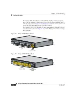
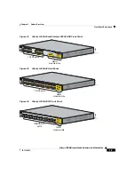
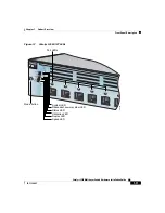
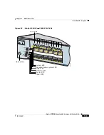
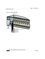
You can use the switch LEDs to monitor switch activity and its performance.
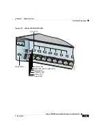
and
show the Catalyst 3550-12T and 3550-12G LEDs and
the Mode button that you use to select one of the port modes.
show the Catalyst 3550-24, 3550-24-DC, 3550-48,
and 3550-24-FX LEDs and the Mode button that you use to select one of the port
modes.
All of the LEDs described in this section except the utilization meter (UTIL) are
visible on the Cluster Management Suite (CMS) home page. The Catalyst 3550
Multilayer Switch Software Configuration Guide describes how to use CMS to
configure and monitor individual switches and switch clusters.


