Design Guide
© 2008 Cisco Systems, Inc. All rights reserved. This document is Cisco Public Information.
Page 19 of 28
Network Topologies Using the Cisco Catalyst Blade Switch 3020
This section discusses the following physical topologies:
●
Recommended topology:
Classic V-shaped topology with Spanning Tree Protocol
●
Alternative topology:
Square topology with Spanning Tree Protocol
These network designs emphasize high availability in the data center by eliminating any single
point of failure and by providing deterministic traffic patterns and predictable behavior during times
of network convergence. The configuration example included uses a pair of Cisco Catalyst 6513
Switches as the aggregation layer platform. This Layer 2/Layer 3 switching platform supports the
slot density and integrated network services required by data centers deploying blade systems. An
HP c-Class BladeSystem with two Cisco Catalyst Blade Switch 3020s composes the Layer 2
access layer.
Recommended Topology
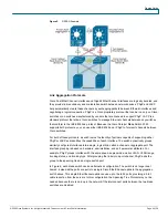
Typical deployment in the data center uses the classic triangle topology. This deployment model
has no single point of failure. The Cisco Catalyst Blade Switch 3020s are dual homed to the
aggregation layer, providing link redundancy. The Spanning Tree Protocol manages the physical
loops created by the uplinks between the aggregation and access switches, facilitating a
predictable and fast-converging topology.
RPVST+ fulfills the high-availability requirements of this design and is the recommended mode of
spanning-tree operation. RPVST+ provides fast convergence (less than 1 second) in device or
uplink failure scenarios. In addition, RPVST+ offers enhanced Layer 2 features for the access layer
with integrated capabilities equivalent to PortFast, UplinkFast, and BackboneFast.
The connection between the two internal blade switches supports local traffic limited to the HP
BladeSystem; for example, clustering applications or management traffic such as remotely mirrored
(RSPAN) traffic. This connection does not carry a publicly accessible subnet (for example, a VLAN
that exists on the uplinks to the aggregation switches). If it did, another set of interfaces would have
to be accounted for in the Spanning Tree Protocol calculations. Therefore, to create a less-complex
Spanning Tree Protocol domain, these cross-connect interfaces are removed from the equation by
clearing the public VLANs from the links.
The HP c-Class BladeSystem server-blade NICs support the logical separation of VLANs by
trunking, allowing each NIC to accommodate the public and the private VLANs on the Cisco
Catalyst Blade Switch 3020s. In addition, full-height servers are dual homed to each of the two
Cisco Catalyst Blade Switch 3020s in the HP BladeSystem. This structural design allows for the
physical separation of public and private VLANs between two NICs homed to the same Cisco
Catalyst Blade Switch 3020.
A series of network-convergence tests was performed to verify and characterize the high-
availability features of the recommended design. These tests consisted of passing traffic between
an external client device and the blade servers while monitoring packet loss. The following test
cases were used:
●
Uplink failure and recovery between switch A and the primary root
●
Uplink failure and recovery between switch B and the primary root
●
Switch A failure and recovery
●
Switch B failure and recovery


