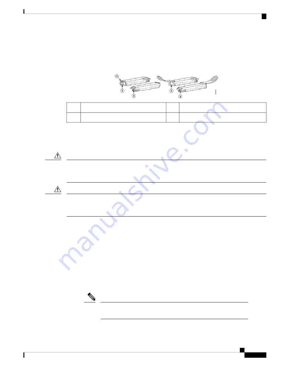
The following figure shows the 40-Gigabit optical QSFP+ transceiver. The transceiver is used primarily in
short reach applications in switches, routers, and data center equipment where it provides higher density than
SFP+ modules. The 100-Gigabit optical QSFP28 transceiver is similar to the 40-Gigabit optical QSFP
transceiver.
Figure 74: 40-Gigabit QSFP+ Transceiver Module (Optical)
Electrical connection to the module circuitry
3
40GBASE QSFP+ transceiver body
1
Bail-clasp latch
2
The QSFP+ or QSFP28 transceiver module can have either a bail-clasp latch or a pull-tab latch. Installation
procedures for both types of latches are provided.
Before you begin
Do not install or remove the QSFP28 module with fiber-optic cables still attached to it. Doing so may damage
cables, cable connectors, or the optical interfaces and may interfere with the QSFP28 module latching properly
into its socket connector. Disconnect all cables before removing or installing an QSFP28 module.
Caution
The QSFP+ or QSFP28 transceiver module is a static-sensitive device. Always use an ESD wrist strap or
similar individual grounding device when handling QSFP+ or QSFP28 transceiver modules or coming into
contact with system modules.
Caution
• Attach an ESD-preventive wrist strap to your wrist and connect the other end to the grounding lug
connected to the chassis.
• You must use the supported QSFP28 modules. The following QSFP28 modules are supported on the
Supervisor PIC:
• QSFP-100G-SR4-S
• QSFP-100G-LR4-S
• QSFP-40G-SR4 with breakout cable
• QSFP-4x10G-LR-S with breakout cable
• QSFP-100G-SM-SR
If the QSFP-100G-SM-SR module is used in the SUP 250 PIC card, the cBR-8
router chassis ambient temperature must be limited to 54ºC at sea level.
Note
Cisco Converged Broadband Routers Hardware Installation Guide
113
Installing the Supervisor in the Cisco cBR Chassis
Installing the QSFP+ or QSFP28 Transceiver Modules in the Supervisor PIC


