2-16
Cisco CGS 2520 Hardware Installation Guide
OL-31444-01
Chapter 2 Switch Installation
Installing the Switch
Wall-Mounting
The following steps are covered in this section:
•
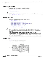
Attaching Brackets for Wall Mounting, page 2-16
•
Wall-Mounting (for IP-30 Compliance), page 2-17
Warning
If the switch is wall-mounted in an enclosure allow for these minimum clearances:
• Sides of switch (facing up and facing down): 3.75 in. (9.52 cm)
• Port side 3.0 in. (7.62 cm)
• Power supply side: 5.25 in. (13.33 cm)
• Cover side (side not facing wall): 1.75 in. (4.44 cm)
• Base side (facing wall): 0 in. (0 cm)
Attaching Brackets for Wall Mounting
Follow these steps to mount the switch onto a wall.
Step 1
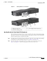
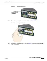
Insert the rubber plugs into the appropriate holes. Follow the same procedure for the other side of the
switch.
Step 2
Use a screwdriver or pen to completely push in the rubber plugs (see
Figure 2-8
).
Step 3
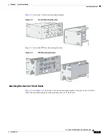
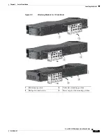
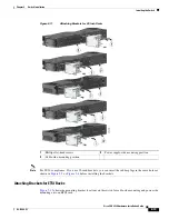
Install the brackets onto both sides of the switch (see
Figure 2-16
).
Step 4
Secure the bracket and switch to the wall using the screws provided.
Figure 2-14
shows how to wall-mount the switch onto a wall.


