3-3
Cisco CGS 2520 Hardware Installation Guide
OL-31444-01
Chapter 3 Power Supply Installation
Power Supply Module Installation
Installation Guidelines
Observe these guidelines when removing or installing a power supply module:
A power supply module that is only partially connected to the switch disrupts the system operation.
Warning
Blank faceplates and cover panels serve three important functions: they prevent exposure to
hazardous voltages and currents inside the chassis; they contain electromagnetic interference (EMI)
that might disrupt other equipment; and they direct the flow of cooling air through the chassis. Do not
operate the system unless all cards, faceplates, front covers, and rear covers are in place.
Statement 1029
Note
You can order the blank cover (part number RPS-CG-COVER=).
Warning
Do not reach into a vacant slot while installing or removing a module. Exposed circuitry is an energy
hazard.
Statement 206
Warning
Only trained and qualified personnel should be allowed to install, replace, or service this equipment.
Statement 1030
Warning
Do not work on the system or connect or disconnect cables during periods of lightning activity.
Statement 1001
Installing a Power Supply Module
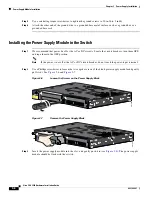
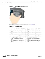
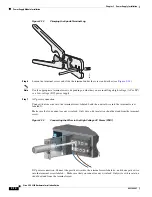
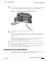
This procedure is for installing a power supply module in the PSU1 or PSU2 slot.
Warning
The covers are an integral part of the safety design of the product. Do not operate the unit without the
covers installed.
Statement 1077
Warning
This unit might have more than one power supply connection. All connections must be removed to
de-energize the unit.
Statement 1028
Caution
Equipment installation must comply with local and national electrical codes.
Equipment That You Need
•
Ratcheting torque flathead screwdriver that exerts up to 15-inch pound (in-lb) of torque
•
Ring, spade, or flanged spade terminal


