B-3
Cisco CGS 2520 Hardware Installation Guide
OL-31444-01
Appendix B Connector and Cable Specifications
Connector Specifications
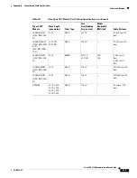
Dual-Purpose Ports
The 10/100/1000 Ethernet ports on the dual-purpose ports use RJ-45 connectors.
Figure B-3
10/100/1000 Port Pinouts
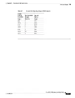
Alarm Port
The alarm port uses an RJ-45 connector. See the
“Alarm Ports” section on page 1-7
for more information.
Figure B-4
Alarm Port Pinouts
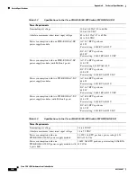
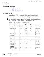
Alarm Ratings
The following lists the alarm rating information
•
Alarm Input Electrical Specification: 8V @ 1mA
•
Alarm Output Electrical Specification: 30V @ 1A
Note
Due the RJ-45 design (connector pin spacing), the alarm output does not support AC voltage.
60915
2 3
1
4 5 6 7 8
Pin
Label
1
2
3
4
5
6
7
8
TP0+
TP0-
TP1+
TP2+
TP2-
TP1-
TP
3
+
TP
3
-
2074
3
4
2 3
1
4 5 6 7 8
Pin
Alarm connection
1
2
3
4
5
6
7
8
Alarm 1 input
Alarm 2 input
Normally closed
Alarm
3
input
Alarm 4 input
Normally open
Alarm output common
Alarm input common

