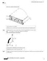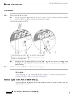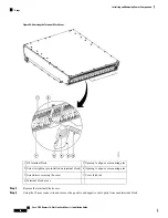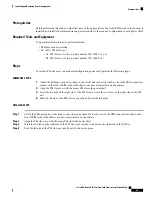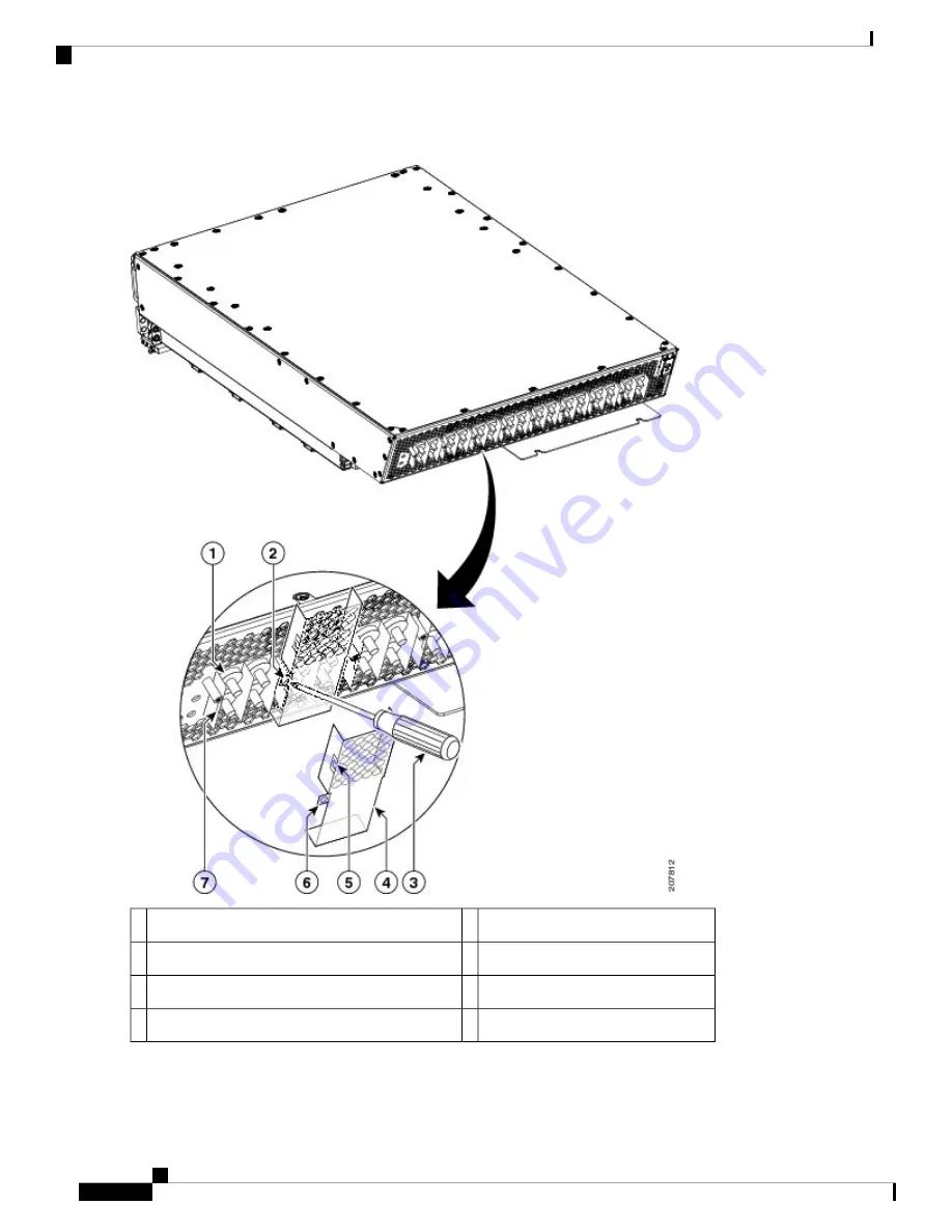
Figure 44: Removing the Terminal Block Cover
Opening to align over mounting pins
5
DC terminal block.
1
Opening to align over mounting pins
6
Screw to tighten (pre-installed on terminal block)
2
Cover latch tab
7
Screwdriver securing the cover
3
Terminal block cover
4
Step 3
Remove the terminal block cover.
Step 4
Using the 10-mm socket wrench, remove the positive and negative cable pairs from each terminal block.
Cisco CRS Routers 16-Slot Line Card Chassis Installation Guide
80
Installing and Removing Power Components
Steps

