C H A P T E R
3
Installing and Removing Air Circulation
Components
This chapter provides instructions on how to install and replace Cisco CRS 16-Slot Line Card Chassis air
circulation components.
The chassis is shipped with the fan trays and air filter pre-installed.
Note
•
Information About Air Circulation Components, on page 99
•
How to Replace Air Circulation Components, on page 100
Information About Air Circulation Components
This section describes the air circulation components: the fan trays and the air filters.
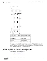
The LCC has two fan trays (show in the figure below), one just below the lower card cage and the other just
above the upper card cage. The chassis can run with only one fan tray operating. If a failure occurs in one fan
tray, the other fan tray acts as the redundant fan tray to assure fault-tolerant system performance; the chassis
continues to operate while the failed fan tray is replaced.
The LCC fan tray operates in either the upper or lower fan tray slots. Each fan tray installs into the rear (MSC)
side of the chassis and contains:
• Nine fans
• Fan tray board
• Front-panel status LED
The upper and lower fan trays are interchangeable and installed in the same manner.
Note
Cisco CRS Routers 16-Slot Line Card Chassis Installation Guide
99


