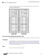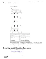
Figure 51: Airflow Through LCC
Power shelves (two installed)
6
Front (PLIM) side of chassis
1
Air exhaust
7
Air intake
2
Upper card cage
8
Lower fan tray
3
Lower card cage
9
Air filter
4
Rear [MSC] side of chassis
10
Upper fan tray
5
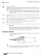
The chassis has a serviceable air filter mounted in a slide-out tray accessible from the front of the chassis just
below the lower card cage (as shown in the figure). The air filter removes dust from the room air drawn into
the router by the two fan trays. Once a month (or more often in dusty environments) you should examine the
air filter and replace it if it appears damaged or excessively dirty.
How to Replace Air Circulation Components
This section contains the following procedures:
•
Replacing a Fan Tray, on page 101
Cisco CRS Routers 16-Slot Line Card Chassis Installation Guide
100
Installing and Removing Air Circulation Components
How to Replace Air Circulation Components

