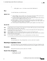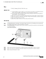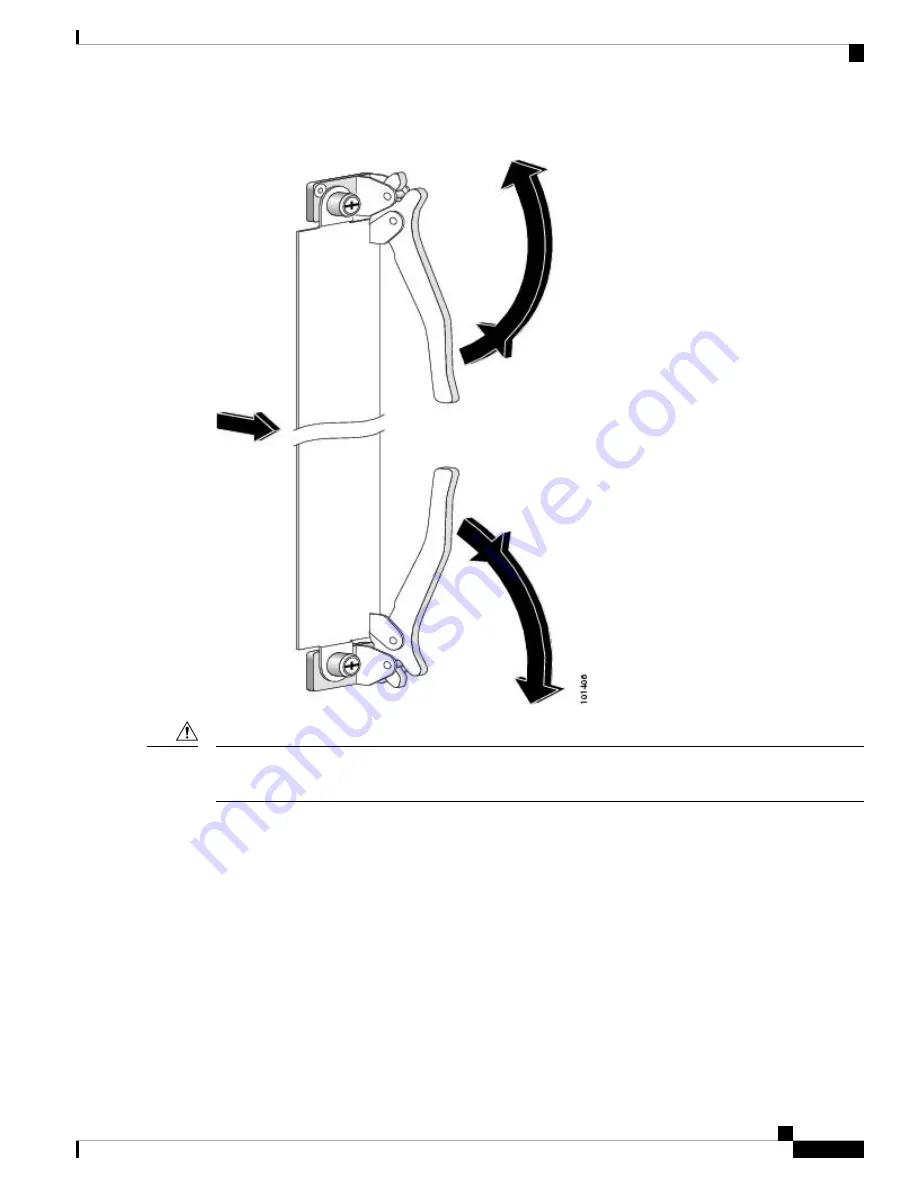
Figure 55: Operating Ejector Levers
When you remove a card, always use the ejector levers to ensure that the connector pins disconnect from the
midplane in the sequence expected by the router.
Caution
• You should install the cards in the following order during the chassis initial installation process:
• Always install cards in the empty slots first from one side to the other. The chassis is shipped with
all slots either containing impedance carriers or covered by slot covers to help maintain chassis
stiffness and ensure that the chassis is undamaged during shipment. See the next section.
• Install the route processor (RP) cards first, the left one before the right one. Tighten the screws only
after fully inserting both RP cards.
• Install the LCC fan controller cards in the same manner.
• Install the switch fabric cards in the same manner, one shelf at a time.
• For an MSC, FP, or LSP line card or a PLIM, remove one impedance carrier, install a functional
board and tighten the screw, and then repeat the process until all line cards and PLIMs have been
installed.
Cisco CRS Routers 16-Slot Line Card Chassis Installation Guide
107
Installing and Removing Line Cards, PLIMs, and Associated Components
Guidelines for Card Installation and Removal


