Verifying the Installation of an RP, PRP, or DRP Card
This section describes how to verify and troubleshoot the installation of a route processor (RP), performance
route processor (PRP), or distributed route processor (DRP) card, and how to verify that the card has been
properly installed.
Figure 82: RP Card Front Panel
Management Ethernet RJ45 port
7
Console port
1
Alphanumeric LED Display
8
Aux port
2
Alphanumeric LED Display
9
Internal hard disk
3
PRIMARY LED—PRP active or standby indicator
10
PC card slot
4
STATUS LED—Card status indicator
11
Control Ethernet 0 port
5
Control Ethernet 1 port
6
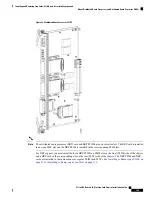
Figure 83: Performance Route Processor Front Panel
Link/Active 0 LED
8
OIR push button—Press to initiate OIR process
1
Control Ethernet 0 port (SFP or SFP+)
9
OIR Ready LED
2
Link/Active 1 LED
10
USB socket
3
Control Ethernet 1 port (SFP or SFP+)
11
Console port
4
Alphanumeric LED Display
12
Auxiliary port
5
PRIMARY LED—PRP active or standby indicator
13
Service Ethernet RJ45 port
6
STATUS LED—Card status indicator
14
Management Ethernet RJ45 port
7
Cisco CRS Routers 16-Slot Line Card Chassis Installation Guide
152
Installing and Removing Line Cards, PLIMs, and Associated Components
Verifying the Installation of an RP, PRP, or DRP Card

