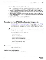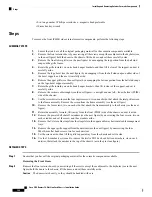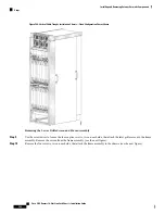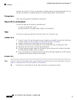
to the rear side of the LCC. The new rear kick panel is installed into the new rear kick panel bracket. The rear
kick panel is available as an orderable option (Cisco Product Number CRS-16-LCC-BCK-KP=).
Prerequisites
There are no prerequisites for installing the rear kick panel.
Required Tools and Equipment
You need the following tool and parts to perform this task:
• 2.5 mm or 3/32-inch Allen wrench
• Rear kick panel kit (Cisco product number: CRS-16-LCC-BCK-KP=)
Steps
To attach the rear kick panel and bracket to the rear of the LCC, follow these steps:
SUMMARY STEPS
1.
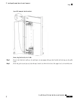
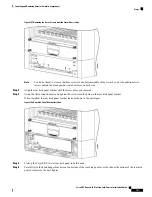
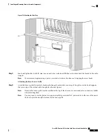
Using a 2.5 mm or 3/32-inch Allen wrench, remove the eight screws from the lower rear bay of the chassis
as shown in
Figure 107: Removing the Set of Screws from the Lower Chassis Bay
.
2.
Align the rear kick panel bracket with the screw holes you removed.
3.
Using the Allen wrench, insert and tighten the screws into the holes in the rear kick panel bracket.
4.
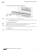
Pick up the Cisco CRS 16-slot rear kick panel in both hands.
5.
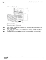
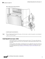
Carefully slot the hook hanger brackets on the bottom of the rear kick panel over the tabs at the bottom
of the rear kick panel bracket (see the next figure).
6.
To secure the top fasteners, firmly press the top edge of the rear kick panel against the top of the rear kick
panel bracket until it snaps onto the ball stud retainers.
DETAILED STEPS
Step 1
Using a 2.5 mm or 3/32-inch Allen wrench, remove the eight screws from the lower rear bay of the chassis as shown in
Figure 107: Removing the Set of Screws from the Lower Chassis Bay
.
To be able to access the bottom screws, the Allen wrench must be no longer than 3 inches.
Tip
Cisco CRS Routers 16-Slot Line Card Chassis Installation Guide
192
Installing and Removing Exterior Cosmetic Components
Prerequisites


