Prerequisites
Before performing these tasks, you must first unpack and secure the chassis. See
Cisco CRS Carrier Routing
System 16-Slot Line Card Chassis Unpacking, Moving, and Securing Guide
. If you purchased the rear cosmetics
package after you installed the chassis, you must remove the rear upper air grille and short vertical brackets
before installing the package. See
Installing the Optional Rear (MSC) Side Cosmetic Components
for more
information.
Required Tools and Equipment
You need the following tool and parts to perform this task:
• 8-in. long number 1 Phillips screwdriver—magnetic head preferable #1
• 2-mm hex key wrench
• Rear vertical cable troughs
• Midchassis cable management bracket
• Rear door strike tube
• Door stop (700-16671-01)
• Lower chassis cosmetic bezel (800-23776-01)
• Rear louver grille (CRS-16-LCC-R-GRL=)
• Rear doors (right—800-25724-01; left—800-24569-01)
Steps
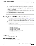
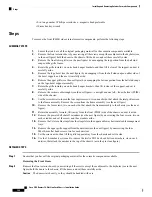
To install the rear (MSC) exterior cosmetic components, follow these steps:
SUMMARY STEPS
1.
Unpack all cosmetic parts to prepare for installation.
2.
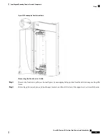
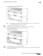
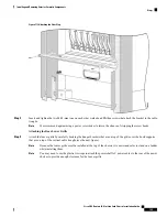
Attach the rear vertical cable troughs—one left and one right—to the rear of the chassis (see the next
figure) by inserting the 22 M4x14-mm flat head screws (11 on each side) and using the screwdriver to
turn the screws clockwise to attach the cable troughs firmly to the chassis. (You might need to use a
ladder to reach the upper screws.)
3.
Attach the mid-chassis horizontal cable management bracket by inserting the four M4 8-mm (two on
each side) wafer-head Phillips screws that attach the bracket to the chassis.
4.
Tighten the screws to the chassis with the medium Phillips screwdriver.
5.
Attach the rear door strike tube (see the previous figure) by inserting the four M4 8-mm wafer-head
Phillips screws through the holes in the face of the strike tube and into the rear (MSC) side of the chassis.
6.
Tighten the four screws to the chassis with the medium Phillips screwdriver.
7.
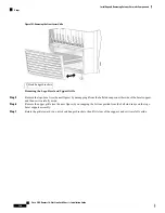
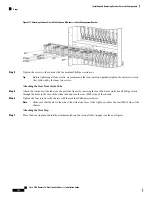
Place the door stop tabs behind the attachment tabs on the vertical cable troughs (see the next figure).
8.
Insert and tighten the two M4 8-mm (one on each side) wafer-head Phillips screws that attach the bracket
to the cable troughs.
9.
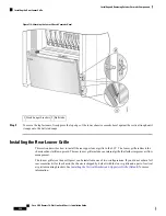
Attach the louver grille by carefully hooking the hanger brackets that are on top of the grille over the
hook supports that are on top of the vertical cable troughs (see the next figure).
10.
Press the louver grille firmly until its ball studs snap onto the ball stud retainers.
11.
Carefully slot the hook hanger brackets on the bottom of the lower chassis cosmetic bezel over the tabs
on the vertical cable troughs.
Cisco CRS Routers 16-Slot Line Card Chassis Installation Guide
195
Installing and Removing Exterior Cosmetic Components
Prerequisites


