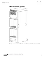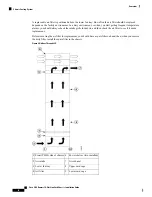
Figure 5: LCC Front (PLIM) Side Slot Numbers—Fixed Configuration Power Shown
The components on the front (PLIM) side of the chassis include:
• Upper power shelf (PS0)
• Lower power shelf (PS1)
• Upper PLIM card cage with eight PLIM slots (left to right: 0, 1, 2, 3 and 4, 5, 6, 7) spaced around two
double-width fan controller card slots, FC0 and FC1. (These thicker-width slots accept only the two fan
controllers.)
• Lower PLIM card cage with eight PLIM slots (left to right: 8, 9, 10, 11 and 12, 13, 14, 15) and two
double-width route processor card slots, RP0 and RP1. (These thicker-width slots accept only the RPs.)
The following figure shows the chassis slot numbers on the rear (MSC) side of the LCC.
Cisco CRS Routers 16-Slot Line Card Chassis Installation Guide
8
Overview
Chassis Slot Numbers


