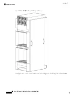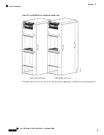
Because no external switch fabric interconnection cabling exists on the single LCC, the rear door is optional.
Note
Chassis Cable Management
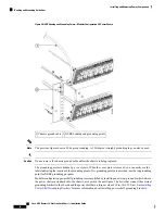
The LCC has cable management features for both the front (PLIM) and rear (MSC) sides of the chassis. The
PLIM side has horizontal cable management features above both card cages. The front horizontal cable
management trays have a special telescoping feature that allows them to be extended when the chassis is
upgraded with higher-density cards. This extension feature also helps when installing the cables in the chassis.
The front cosmetic doors need to be removed from the chassis when the telescoping feature is in use.
Note
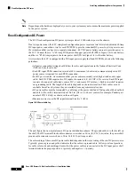
The MSC side of the chassis has one cable management system above the lower card cage (in the middle of
the chassis). These rear cable management trays are not telescoping because there is a preset amount of fiber
cabling to be managed.
Chassis Exterior Components
The LCC also includes front and rear locking doors, bezels, and side panels. The front and rear doors are
optional in the standalone system. The cosmetic components are shipped in a separate package and must be
installed on the LCC during system installation.
Chassis Cooling System
The LCC cooling system includes the components and control system that draw ambient air through the system
to dissipate heat and keep the system operating in a desired temperature range. The complete LCC cooling
system includes:
• Two fan trays
• Two fan controller cards
• Temperature sensors distributed on cards and modules in the chassis
• Operating software that controls the cooling system
• Air filter
• Inlet and outlet air vents and bezels
• Impedance carriers for empty chassis slots
• Power module cooling fans
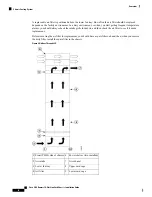
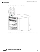
The airflow through the LCC is controlled by a push-pull configuration. As shown in the figure below, ambient
air flows in at the bottom front (PLIM) side and up through the card cages until it exhausts at the top rear
(MSC) side of the LCC. The bottom fan tray pulls ambient air in from the bottom front of the chassis; the top
fan tray pushes warm air out the back of the chassis. The power modules in the power shelves have their own
self-contained cooling fans.
Cisco CRS Routers 16-Slot Line Card Chassis Installation Guide
11
Overview
Chassis Cable Management

