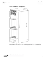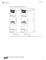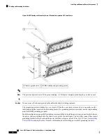
Figure 9: NEBS Bonding and Grounding Points—Modular Configuration DC Power Shown
NEBS bonding and grounding points
2
Chassis ground cable
1
The previous figure shows a 45-degree grounding. A 180-degree (straight) grounding lug can also be used.
Note
Do not remove the chassis ground cable unless the chassis is being replaced.
Caution
The grounding points are hidden by a cover plate. When the cover plate is removed, you can easily see the
labels indicating the location of the grounding points. Two grounding points are provided; use the top grounding
point for NEBS grounding purposes.
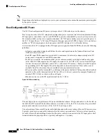
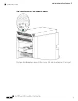
Modular configuration power shelf grounding is accomplished by installing an external ground bracket between
the power shelves and attached to the chassis, as shown in the next figure. The bolts that connect the external
grounding brackets to the chassis and the power shelf have a torque value of 30 in.-lb (3.39 N-m). See
Power Shelf Grounding Brackets
for more information about installing power shelf grounding brackets.
Cisco CRS Routers 16-Slot Line Card Chassis Installation Guide
18
Installing and Removing Power Components
Bonding and Grounding Guidelines

