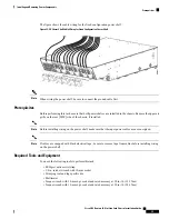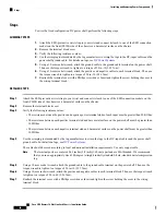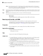
3.
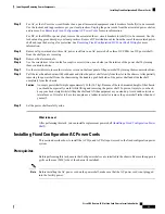
Seat the alarm module in the power shelf backplane by pressing it firmly into the chassis backplane
connector.
4.
Use the screwdriver to turn the captive screw at the bottom of the alarm module clockwise to seat the
alarm module connectors in the connectors on the power shelf interface panel.
DETAILED STEPS
Step 1
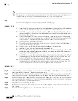
Attach the ESD-preventive wrist strap to your wrist and connect its leash to one of the ESD connection sockets on the
front (PLIM) side of the chassis or a bare metal surface on the chassis.
To prevent damage to the backplane connector on the alarm module, do not use excessive force when inserting
the alarm module into its power shelf bay.
Caution
Step 2
Using two hands to support and guide the alarm module, slide it into the far right bay on the power supply shelf until the
connector on the back of the alarm module makes contact with the connector on the backplane of the shelf. Verify that
the guide pin on the chassis front panel is correctly aligned with the hole on the front of the alarm module.
The alarm module weighs approximately 4.2 lb (2 kg). Because of the rack-mounted height of the chassis, you
should be especially careful while lifting and removing the alarm module. Use two hands when handling the
alarm module. It is safer to use a ladder to install or remove the alarm module.
Caution
Step 3
Seat the alarm module in the power shelf backplane by pressing it firmly into the chassis backplane connector.
Step 4
Use the screwdriver to turn the captive screw at the bottom of the alarm module clockwise to seat the alarm module
connectors in the connectors on the power shelf interface panel.
What to do next
After performing this task, replace the upper grille on the front (PLIM) side of the chassis.
Removing a Fixed Configuration Alarm Module
This section describes how to remove the alarm module from a fixed configuration power supply in the LCC.
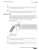
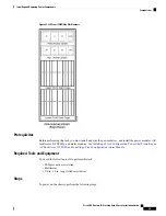
The alarm module is installed only in the far right slot of the power shelf (as you are facing the front [PLIM]
side of the chassis). This
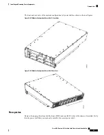
Figure 24: Fixed Configuration Alarm Module
shows a fixed configuration alarm
module.
Prerequisites
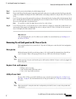
Before performing this task, remove any the upper air grille on the front (PLIM) side of the chassis.
Required Tools and Equipment:
• ESD-preventive wrist strap
• 6-in long number 1 Phillips screwdriver
Steps
To remove an alarm module, perform the following steps:
Cisco CRS Routers 16-Slot Line Card Chassis Installation Guide
47
Installing and Removing Power Components
Removing a Fixed Configuration Alarm Module

