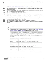
Function or Meaning
Color
LED Name
PEM is in an over temperature condition and shutdown has occurred.
Yellow
OT
PEM I/O switch is in the OFF position.
Yellow
CBREAKER TRIP
Converting from One Fixed Configuration Power System to Another
This section describes how to convert from one fixed configuration power system to another (either from
fixed AC to fixed DC or from fixed DC to fixed AC).
Steps
To convert an LCC with a fixed configuration power system from AC to DC power, or from DC to AC power,
perform the following steps:
SUMMARY STEPS
1.
Power down the chassis completely. See
Powering Up and Down a Chassis with Fixed Configuration
or
Power Up and Power Down a Chassis with Fixed Configuration DC Power
.
2.
Remove the alarm modules. See
Removing a Fixed Configuration Alarm Module
.
3.
Remove the DC PEMs or AC rectifiers. See
Removing an AC rectifier or DC PEM
.
4.
Unplug the AC power cords or remove the DC fusing from the power source. Remove the AC or DC
wiring from the rear of the fixed configuration power shelf. Remove the AC power cords or DC wiring
and ground wire from the rear of the fixed configuration power shelves. See
and
Removing Fixed Configuration DC Power Shelf Wiring
5.
Remove both power shelves. See
Removing a Fixed Configuration Power Shelf
6.
Install the new power shelves. See
Installing a Fixed Configuration Power Shelf
7.
Install the wiring on the rear of the power shelf. See
Installing Fixed Configuration AC Power Cords
section on page 2-20 or
Installing Fixed Configuration DC Power Shelf Wiring
8.
Install the DC PEMs or AC rectifiers. See
Installing an AC Rectifier or DC PEM
.
9.
Install the alarm module. See
Installing a Fixed Configuration Alarm Module
10.
Replace the DC fuses or restore AC service.
11.
Power the chassis back up. See
Powering Up and Down a Chassis with Fixed Configuration AC Power
or
Power Up and Power Down a Chassis with Fixed Configuration DC Power
DETAILED STEPS
Step 1
Power down the chassis completely. See
Powering Up and Down a Chassis with Fixed Configuration AC Power
or
Power Up and Power Down a Chassis with Fixed Configuration DC Power
Step 2
Remove the alarm modules. See
Removing a Fixed Configuration Alarm Module
Step 3
Remove the DC PEMs or AC rectifiers. See
Removing an AC rectifier or DC PEM
.
Step 4
Unplug the AC power cords or remove the DC fusing from the power source. Remove the AC or DC wiring from the
rear of the fixed configuration power shelf. Remove the AC power cords or DC wiring and ground wire from the rear
of the fixed configuration power shelves. See
Removing Fixed Configuration AC Power Cords
and
Configuration DC Power Shelf Wiring
Step 5
Remove both power shelves. See
Removing a Fixed Configuration Power Shelf
.
Cisco CRS Routers 16-Slot Line Card Chassis Installation Guide
56
Installing and Removing Power Components
Converting from One Fixed Configuration Power System to Another


