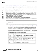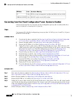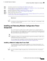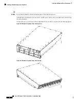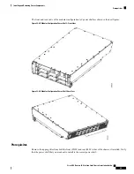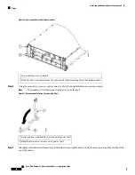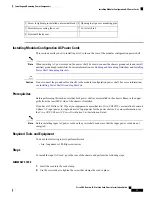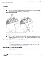
Top mounting screw in handle.
1
Holes for the screw that attaches the power shelf to the mounting block though the handle.
2
What to do next
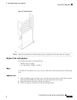
After the modular configuration power shelves are installed in the chassis, install the grounding lug and
brackets, and AC or DC power shelf wiring. Continue to
Installing Power Shelf Grounding Brackets
and
Installing AC or DC Power Shelf Wiring
for instructions
.
Removing a Modular Configuration Power Shelf
This section describes how to remove the modular configuration power shelf from the LCC.
Prerequisites
Before performing this task, remove the upper grilles from the front (PLIM) and rear (MSC) sides of the
chassis (if installed), the AC or DC PMs, alarm module, AC or DC input power wiring from the shelf that
you want to disconnect, and power shelf grounding brackets. For more information, see
Removing a Modular Configuration Alarm Module
, and
Removing Power Shelf Grounding Brackets
.
Required Tools and Equipment
• 6 in. long number 1 Phillips screwdriver
• 10-mm 6 pt. combination wrench
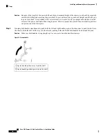
Do not use the handles for lifting or supporting the power shelf, because this could severely damage the
handles.
Caution
Do not bend the handles sideways during any part of the removal process.
Caution
Steps
To remove a modular configuration power shelf, perform the following steps:
SUMMARY STEPS
1.
Using the wrench, loosen the two bolts on the rear of the chassis that clamp the rear of the power shelf to
the chassis.
2.
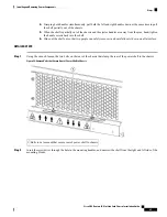
Insert the screwdriver through the hole in the mounting handles, and unscrew the shelf from the right and
left side of the mounting blocks.
3.
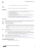
Using the screwdriver, unscrew captive screw on the left and right handles (see previous figure).
Cisco CRS Routers 16-Slot Line Card Chassis Installation Guide
64
Installing and Removing Power Components
Removing a Modular Configuration Power Shelf


