3.
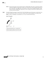
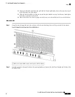
Attach the shelf grounding bracket to both power shelves using the four M6 hex head bolts provided. Do
not tighten (see the next figure).
4.
Attach the grounding L-bracket to the shelf grounding bracket using the two M6 hex nuts provided. Do
not tighten (see the next figure).
5.
Attach the grounding L-bracket to the chassis using the two M6 hex bolts provided. Using the torque
wrench, tighten the M6 hex bolts to a torque of 20 in.-lb (2.26 N-m).
6.
Using the torque wrench, tighten the four M6 hex bolts attaching the grounding bracket to the power
shelves to a torque of 20 in.-lb (2.26 N-m).
7.
Using the torque wrench, tighten the two M6 hex nuts attaching the grounding L-bracket to the power
shelf to a torque of 20 in.-lb (2.26 N-m).
DETAILED STEPS
Step 1
Attach the ESD-preventive wrist strap to your wrist and connect its leash to one of the ESD connection sockets on the
front (PLIM) side of the chassis or a bare metal surface on the chassis.
Step 2
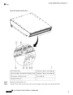
Align the shelf grounding bracket with the power shelves.
Step 3
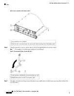
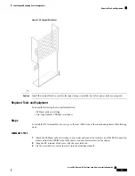
Attach the shelf grounding bracket to both power shelves using the four M6 hex head bolts provided. Do not tighten (see
the next figure).
Step 4
Attach the grounding L-bracket to the shelf grounding bracket using the two M6 hex nuts provided. Do not tighten (see
the next figure).
Cisco CRS Routers 16-Slot Line Card Chassis Installation Guide
68
Installing and Removing Power Components
Steps


