Prerequisites
Before performing this task, you must first remove the upper grille on the front (PLIM) side of the chassis, if
installed.
Required Tools and Equipment
You need the following tools to perform this task:
• ESD-preventive wrist strap
• 6-in. long number 1 Phillips screwdriver
Steps
To remove a PM from a modular configuration power shelf, perform the following steps:
SUMMARY STEPS
1.
Attach the ESD-preventive wrist strap to your wrist and connect its leash to one of the ESD connection
sockets on the front (PLIM) side of the chassis or a bare metal surface on the chassis.
2.
Remove the upper grille on the front (PLIM) side of the chassis. For detailed instructions, go to
Installing
and Removing Exterior Cosmetic Components
.
3.
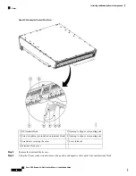
Using the screwdriver, unscrew the ejector from the PM.
4.
Flip down the ejector, slide the PM out of the power shelf, and carefully place it down on a flat surface.
DETAILED STEPS
Step 1
Attach the ESD-preventive wrist strap to your wrist and connect its leash to one of the ESD connection sockets on the
front (PLIM) side of the chassis or a bare metal surface on the chassis.
Step 2
Remove the upper grille on the front (PLIM) side of the chassis. For detailed instructions, go to
Installing and Removing
Exterior Cosmetic Components
.
Step 3
Using the screwdriver, unscrew the ejector from the PM.
Step 4
Flip down the ejector, slide the PM out of the power shelf, and carefully place it down on a flat surface.
What to do next
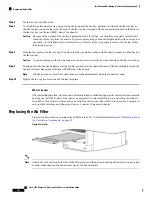
After performing this task, install a replacement AC or DC PM if necessary (see
) and re-install the upper grille on the front (PLIM) side of the chassis.
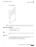
Installing a Power Module Slot Cover
This section describes how to install power module slot covers, in empty power module slots in the power
shelves installed in the LCC.
Although the AC and DC power module slot covers differ slightly in size, they are installed using the same
procedures.
Cisco CRS Routers 16-Slot Line Card Chassis Installation Guide
88
Installing and Removing Power Components
Prerequisites

