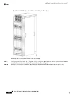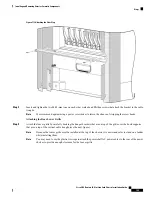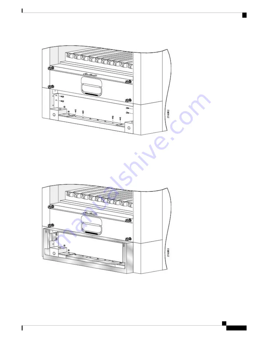
Figure 107: Removing the Set of Screws from the Lower Chassis Bay
You do not need to remove the three screws in the bottom middle of the lower bay, nor the additional two
screws behind the black powder-coated surfaces on each side.
Note
Step 2
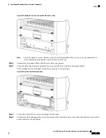
Align the rear kick panel bracket with the screw holes you removed.
Step 3
Using the Allen wrench, insert and tighten the screws into the holes in the rear kick panel bracket.
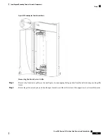
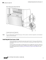
When installed, the rear kick panel bracket looks as shown in the next figure.
Figure 108: Rear Kick Panel Bracket Installed
Step 4
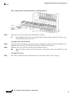
Pick up the Cisco CRS 16-slot rear kick panel in both hands.
Step 5
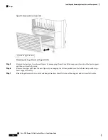
Carefully slot the hook hanger brackets on the bottom of the rear kick panel over the tabs at the bottom of the rear kick
panel bracket (see the next figure).
Cisco CRS Routers 16-Slot Line Card Chassis Installation Guide
193
Installing and Removing Exterior Cosmetic Components
Steps


