background image

Power Up and Power Down a Chassis with Fixed Configuration DC Power

This section describes how to power up and power down an LCC with fixed configuration DC power shelves
installed. For details on the chassis power systems, see

Basic Chassis Power Details

and

DC Power Systems

.

Each power shelf in the LCC has its own I/O switch for shelf power cutoff. The LCC as a whole does not
have a single power switch that powers the entire chassis and all its components up and down. Power shelf
linkage cuts power to the chassis as a whole when both power shelves are turned off.

Most components on the chassis, such as the power shelves, power modules, alarm modules, and fan trays,
can be removed or installed in the chassis while it is running. Although it is possible to install or remove a
power shelf while the chassis is running, it is recommended to remove power from the chassis completely, if
possible, for service protection and safety.

Although the chassis can be powered on by switching on the two power shelf I/O switches (if all individual
power rectifier I/O switches are in the ON position), this method draws a large power surge on start-up. We
recommend following the procedure outlined below to power the chassis on and off.

Note

Prerequisites

Before performing this task, you must install and wire the power shelves, install the DC PEMs and alarm
modules. See

Installing a Fixed Configuration Power Shelf

,

Installing an AC Rectifier or DC PEM

and

Installing a Fixed Configuration Alarm Module

. Wiring at the BDFB or at the power plant should be complete.

Make sure all PEM, power shelf, and power source circuit breakers and switches are turned off (or open)
before you wire the power shelves.

Note

Required Tools and Equipment

• ESD-preventive wrist strap
• Multimeter

Steps

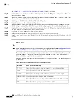
To power on the chassis, perform the following steps:

SUMMARY STEPS

1.

Attach the ESD-preventive wrist strap to your wrist and connect its leash to one of the ESD connection
sockets on the front (PLIM) side of the chassis or a bare metal surface on the chassis.

2.

Verify that the safety ground wiring is connected to the upper (PS0) and lower (PS1) power shelves.

3.

Make sure that the facility power breakers for the upper (PS0) and lower (PS1) power shelves are in
the OFF position.

4.

Make sure all the I/O switches are in an OFF position. That is, make sure all power levers are pulled
out. There are total of six power levers for the DC PEMs (one for each of the six DC PEMs) and two
power levers for the DC power shelves (one for each power shelf).

Cisco CRS Routers 16-Slot Line Card Chassis Installation Guide

53

Installing and Removing Power Components

Power Up and Power Down a Chassis with Fixed Configuration DC Power

Summary of Contents for CRS-16-LCC/M

Page 1: ...Chassis Installation Guide First Published 2013 08 25 Last Modified 2016 10 21 Americas Headquarters Cisco Systems Inc 170 West Tasman Drive San Jose CA 95134 1706 USA http www cisco com Tel 408 526 4000 800 553 NETS 6387 Fax 408 527 0883 ...

Page 2: ... IMPLIED INCLUDING WITHOUT LIMITATION THOSE OF MERCHANTABILITY FITNESS FOR A PARTICULAR PURPOSE AND NONINFRINGEMENT OR ARISING FROM A COURSE OF DEALING USAGE OR TRADE PRACTICE IN NO EVENT SHALL CISCO OR ITS SUPPLIERS BE LIABLE FOR ANY INDIRECT SPECIAL CONSEQUENTIAL OR INCIDENTAL DAMAGES INCLUDING WITHOUT LIMITATION LOST PROFITS OR LOSS OR DAMAGE TO DATA ARISING OUT OF THE USE OR INABILITY TO USE T...

Page 3: ...Chassis Cable Management 11 Chassis Exterior Components 11 Chassis Cooling System 11 Chassis Power System 13 Safety Guidelines 13 Preventing Electrostatic Discharge 14 Installing and Removing Power Components 15 C H A P T E R 2 Power Systems Overview 15 Power Component Information Common to the Two Types of Power Systems 16 Basic Chassis Power Details 16 Bonding and Grounding Guidelines 17 Install...

Page 4: ...nfiguration Power Shelf 31 Prerequisites 32 Required Tools and Equipment 32 Steps 32 Installing Fixed Configuration AC Power Cords 33 Prerequisites 33 Required Tools and Equipment 34 AC Wye Power Shelf 34 AC Delta Power Shelf 35 Removing Fixed Configuration AC Power Cords 37 Prerequisites 37 Required Tools and Equipment 37 AC Wye Power Shelf 37 AC Delta Power Shelf 38 Installing Fixed Configuratio...

Page 5: ...7 Steps 47 Powering Up and Down a Chassis with Fixed Configuration AC Power 48 Prerequisites 49 Required Tools and Equipment 49 Steps 49 Power Up and Power Down a Chassis with Fixed Configuration DC Power 53 Prerequisites 53 Required Tools and Equipment 53 Steps 53 Converting from One Fixed Configuration Power System to Another 56 Steps 56 Installing and Removing Modular Configuration Power Compon...
Page 6: ...3 Steps 74 Installing DC Terminal Block Covers 74 Required Tools and Equipment 75 Steps 75 Installing Modular Configuration AC Power Cords 77 Prerequisites 77 Required Tools and Equipment 77 Steps 77 Removing AC or DC Power Shelf Wiring 78 Removing Modular Configuration DC Power Shelf Wiring 79 Prerequisites 79 Required Tools and Equipment 79 Steps 79 Removing Modular Configuration AC Power Shelf ...

Page 7: ...emoving a Power Module Slot Cover 90 Prerequisites 90 Required Tools and Equipment 91 Steps 91 Power Up and Power Down a Chassis with Modular Configuration Power 91 Power Up a Chassis with Modular Configuration Power 92 Prerequisites 92 Steps 92 Power Down a Chassis with Modular Configuration Power 94 Steps 94 Converting from One Modular Configuration Power System to Another 95 Steps 95 Converting...

Page 8: ...and Removal 105 About Impedance Carriers and Slot Covers 108 About Hard Drives and PCMCIA Cards 111 About Cable Management Brackets 112 Installing or Removing a Slot Cover 113 Installing a Slot Cover 113 Prerequisites 114 Required Tools and Equipment 114 Steps 114 Removing a Slot Cover 114 Prerequisites 115 Required Tools and Equipment 115 Steps 115 Installing or Removing an Impedance Carrier 115 ...

Page 9: ...ed Tools and Equipment 127 Steps 127 Verifying the Installation of a Switch Fabric Card 129 Understanding the Alphanumeric LEDs 129 Troubleshooting the Switch Fabric Card 129 Installing or Removing a Line Card 130 Installing an MSC FP or LSP Line Card 130 Prerequisites 131 Required Tools and Equipment 132 Steps 132 Removing an MSC FP or LSP Line Card 134 Prerequisites 134 Required Tools and Equipm...

Page 10: ...buted Route Processors and Distributed Route Processor PLIMs 144 Installing an RP PRP or DRP Card 146 Prerequisites 147 Required Tools and Equipment 147 Steps 147 Removing an RP PRP or DRP Card 150 Prerequisites 150 Required Tools and Equipment 151 Steps 151 Verifying the Installation of an RP PRP or DRP Card 152 Understanding the Alphanumeric LEDs 153 Troubleshooting the RP PRP or DRP Card 153 In...

Page 11: ...teps 164 Removing an RP PCMCIA Card 165 Prerequisites 165 Required Tools and Equipment 165 Steps 165 What to Do Next 166 Installing or Removing Optical Modules 166 Installing or Removing a Cable Management Bracket 166 Installing a Cable Management Bracket 166 Prerequisites 167 Required Tools and Equipment 167 Steps 167 Removing a Cable Management Bracket 168 Prerequisites 168 Required Tools and Eq...

Page 12: ...Optional 191 Prerequisites 192 Required Tools and Equipment 192 Steps 192 Installing the Optional Rear MSC Side Cosmetic Components 194 Prerequisites 195 Required Tools and Equipment 195 Steps 195 Installing the Lower Chassis Cosmetic Bezel 203 Installing the Rear Louver Grille 204 Prerequisites 205 Required Tools and Equipment 205 Steps 205 Removing the Default Rear MSC Cosmetic Components 206 Re...

Page 13: ...ly Attached Upper Rear Grille 222 Prerequisites 223 Steps 223 Removing the Upper Fan Tray 224 Prerequisites 224 Required Tools and Equipment 224 Steps 224 Installing the Exhaust Baffle 225 Prerequisites 225 Required Tools and Equipment 225 Steps 225 Reinstalling the Upper Fan Tray 229 Prerequisites 229 Required Tools and Equipment 230 Steps 230 Technical Specifications 233 C H A P T E R 7 Line Car...

Page 14: ...Product IDs 241 C H A P T E R 8 Chassis Product IDs 241 Fabric Cables 246 Cisco CRS Routers 16 Slot Line Card Chassis Installation Guide xiv Contents ...

Page 15: ... on page xv Documentation Conventions on page xv Related Documentation on page xvii Changes to This Document on page xvii Obtaining Documentation and Submitting a Service Request on page xviii Audience This guide is intended for LCC installers and Cisco installation partners who are responsible for installing the LCC components The chassis installers are expected to have installed networking hardw...

Page 16: ...Means reader take note Notes contain helpful suggestions or references to material not covered in the manual Note Means the following information will help you solve a problem The tips information might not be troubleshooting or even an action but could be useful information similar to a Timesaver Tip Means reader be careful In this situation you might perform an action that could result in equipm...

Page 17: ...uting System Packet over SONET SDH Physical Layer Interface Module Installation Note For a complete listing of software documentation available refer to About Cisco IOS XR Software Documentation available online at http cisco com en US products ps5763 tsd_products_support_series_home html Changes to This Document The table lists the technical changes made to this document since it was first printe...

Page 18: ... chapter July 2007 Added a description of the input power present LEDs Added Installing the Inlet Grille Screen Installing the Exhaust Bag and Removing Exterior Cosmetic Components January 2007 Removed Chapter 2 Unpacking and Securing the Line Card Chassis transferred the information to the Cisco CRS 16 Slot Line Card Chassis Unpacking Moving and Securing Guide April 2006 Updated Chapter 2 Unpacki...

Page 19: ...ised Cisco technical documentation as an RSS feed and delivers content directly to your desktop using a reader application The RSS feeds are a free service and Cisco currently supports RSS Version 2 0 Cisco CRS Routers 16 Slot Line Card Chassis Installation Guide xix Preface Preface ...

Page 20: ...Cisco CRS Routers 16 Slot Line Card Chassis Installation Guide xx Preface Preface ...

Page 21: ...System Chassis Power System Safety Guidelines Preventing Electrostatic Discharge Chassis Overview on page 1 Chassis Components on page 2 Chassis Slot Numbers on page 7 Chassis Footprint on page 10 Chassis Cable Management on page 11 Chassis Exterior Components on page 11 Chassis Cooling System on page 11 Chassis Power System on page 13 Safety Guidelines on page 13 Preventing Electrostatic Discharg...

Page 22: ...The LCC is secured to the floor and has locking front and rear doors the front and rear doors are optional For safety the chassis must be secured following the installation procedures for the site Note Chassis Components This section lists the main components of an LCC It primarily identifies the components considered field replaceable units FRUs but where additional detail is useful identifies su...

Page 23: ... fabric cards provide switch fabric components for the system The switch fabric receives user data from one MSC FP or LSP and PLIM pair and performs the switching necessary to route the data to the appropriate egress MSC FP or LSP and PLIM pair As a single shelf standalone system the LCC contains switch fabric cards that provide all three stages of the three stage Benes switch fabric As part of a ...

Page 24: ...de View Fixed Configuration Power This figure shows the rear view of an LCC with a fixed configuration AC and DC power system installed Cisco CRS Routers 16 Slot Line Card Chassis Installation Guide 4 Overview Chassis Components ...

Page 25: ...View Fixed Configuration Power This figure shows the front view of an LCC with a modular configuration AC and DC power system installed Cisco CRS Routers 16 Slot Line Card Chassis Installation Guide 5 Overview Chassis Components ...

Page 26: ... View Modular Configuration Power This figure shows the rear view of an LCC with a modular configuration AC and DC power system installed Cisco CRS Routers 16 Slot Line Card Chassis Installation Guide 6 Overview Chassis Components ...

Page 27: ...ifies the locations and slot numbers for major cards and modules primarily the field replaceable units that plug into the chassis This figure shows the chassis slot numbers on the front PLIM side of the LCC Cisco CRS Routers 16 Slot Line Card Chassis Installation Guide 7 Overview Chassis Slot Numbers ...

Page 28: ...uble width fan controller card slots FC0 and FC1 These thicker width slots accept only the two fan controllers Lower PLIM card cage with eight PLIM slots left to right 8 9 10 11 and 12 13 14 15 and two double width route processor card slots RP0 and RP1 These thicker width slots accept only the RPs The following figure shows the chassis slot numbers on the rear MSC side of the LCC Cisco CRS Router...

Page 29: ...rs are reversed from the PLIM slot numbers on the other side of the chassis Because an MSC is associated and actually mates through the midplane with a PLIM MSC slot 0 is on the far right side of the chassis looking at it from the rear MSC side PLIM slot 0 is on the far left side of the chassis looking at it from the front PLIM side MSC slot 0 and PLIM slot 0 mate with each other through the midpl...

Page 30: ...aisle space required for the installation and maintenance of an LCC This figure is a top view of the LCC footprint with optional front and rear cosmetics installed Figure 7 Top View of LCC Depth of LCC with doors attached and closed 40 2 in 102 2 cm 1 Depth of front cable management to rear cable management excluding doors 38 3 in 97 2 cm 2 From front surface to rear surface of chassis excl cable ...

Page 31: ...nal in the standalone system The cosmetic components are shipped in a separate package and must be installed on the LCC during system installation Chassis Cooling System The LCC cooling system includes the components and control system that draw ambient air through the system to dissipate heat and keep the system operating in a desired temperature range The complete LCC cooling system includes Two...

Page 32: ... the air filter to see if it needs replacement Before removing the air filter for replacement you should have a spare filter on hand then when you remove the dirty filter install the spare filter in the chassis Figure 8 Airflow Through LCC Power shelves two installed 6 Front PLIM side of chassis 1 Air exhaust 7 Air intake 2 Upper card cage 8 Lower fan tray 3 Lower card cage 9 Air filter 4 Cisco CR...

Page 33: ...sco CRS Carrier Routing System before installing configuring or troubleshooting any installed card Note Never attempt to lift an object that might be too heavy for you to lift by yourself Keep the work area clear and dust free during and after installation Do not allow dirt or debris to enter into any laser based components Keep tools and router components away from walk areas Do not wear loose cl...

Page 34: ...SD damage Always use an ESD preventive wrist or ankle strap and ensure that it makes good skin contact Connect the equipment end of the connection cord to an ESD connection socket on the router or to a bare metal surface on the chassis Handle a card by its ejector levers when applicable or its metal carrier only avoid touching the board or connector pins Place a removed card board side up on an an...

Page 35: ...ower components are not interchangeable between the fixed and modular configuration power system Fixed configuration power system Consists of two power shelves DC power entry modules PEMs or AC rectifiers and alarm modules It is available in versions for DC and AC power supplies The AC version requires either 3 phase AC Delta or 3 phase AC Wye input power to the power shelves It provides power sha...

Page 36: ...ecommendations when planning power connections to the router Check the power at your site before installation and periodically after installation to ensure that you are receiving clean power Install a power conditioner if necessary Install proper grounding to avoid damage from lightning and power surges The LCC requires that at least one power shelf and its components be installed to operate prope...

Page 37: ...und inserts are located on top of the chassis rear MSC side panel to the left of the lower power shelf The following figure shows the NEBS and grounding points on the rear MSC side of the chassis with a modular configuration DC power shelf installed This grounding point is also referred to as the network equipment building system NEBS bonding and grounding stud The location of the grounding points...

Page 38: ...rounding points Two grounding points are provided use the top grounding point for NEBS grounding purposes Modular configuration power shelf grounding is accomplished by installing an external ground bracket between the power shelves and attached to the chassis as shown in the next figure The bolts that connect the external grounding brackets to the chassis and the power shelf have a torque value o...

Page 39: ... ground lug to chassis 2 Four M6 hex bolts attaching shelf grounding bracket to power shelves 7 Shelf grounding bracket 3 Two M6 hex bolts attaching grounding L bracket to chassis 4 Installing the Chassis Ground Cable This section describes how to install the ground cable on the LCC Cisco CRS Routers 16 Slot Line Card Chassis Installation Guide 19 Installing and Removing Power Components Installin...

Page 40: ...AWG or larger multi strand copper wire The grounding lug used can be either a 180 degree straight lug or a 45 degree lug Figure 11 180 Degree Straight Chassis Ground Lug Figure 12 45 Degree Chassis Ground Lug Two M6 hex head bolts and integrated locking washers are pre installed on the chassis Cisco CRS Routers 16 Slot Line Card Chassis Installation Guide 20 Installing and Removing Power Component...

Page 41: ...anel as shown Figure 9 NEBS Bonding and Grounding Points Modular Configuration DC Power Shown Then use the torque wrench to tighten to a torque of 30 in lb 3 39 N m DETAILED STEPS Step 1 Use the crimping tool mandated by the lug manufacturer to crimp the lug to the ground cable Step 2 Using the 10 mm wrench attach the ground cable to the grounding point on top of the chassis rear MSC side panel as...

Page 42: ...puts of nominal 48 60 VDC 60 A service Each DC input consists of one pair of cable leads source DC and source DC return Each power shelf requires one grounding cable The length of the cables depends on the router location These cables are not available from Cisco Systems they are available from any commercial vendor DC power cables must be terminated by cable lugs at the power shelf end The lugs s...

Page 43: ...ut line current 168 A peak at 75 VDC maximum for 1 ms Inrush current Each wiring block on the fixed configuration power shelf contains two sets of terminals one positive and one negative and is covered by a plastic block cover that snaps onto the power shelf and is secured by a screw to a torque value of 4 to 5 in lb 0 46 to 0 58 N m You must remove the block cover or rotate it out of the way befo...

Page 44: ... configuration DC input current and voltage specifications Table 3 DC Input Current and Voltage Information 48 VDC North America 60 VDC European Community range 40 VDC to 72 VDC Nominal input voltage 50 A maximum at 48 VDC40 A maximum at 60 VDC60 A maximum at 40 VDC Input line current Each wiring block on the modular configuration DC power shelf contains two sets of terminals one positive and one ...

Page 45: ...ackets to the chassis and the power shelf have a torque value of 30 in lb 3 39 N m Input Power Present LEDs In both power configurations the DC input power present LEDs provide a visual indication to service personnel that there is voltage present across the input terminal connection The LED provides a warning to the service person that there is power present Power should be disconnected before se...

Page 46: ...ion DC Power Shown This figure shows the input power present LEDs on the rear of the modular configuration DC power shelf Cisco CRS Routers 16 Slot Line Card Chassis Installation Guide 26 Installing and Removing Power Components Input Power Present LEDs ...

Page 47: ... powered chassis contains two AC power shelves for 2N redundancy The shelves contain the input power connectors In the fixed configuration power system each shelf contains three AC power rectifiers The power shelves and AC power rectifiers are field replaceable Each shelf and AC power rectifier has its own circuit breaker In the modular configuration power system each shelf can contain up to six A...

Page 48: ...nnection is required for each power shelf The power cord for the fixed configuration AC power shelf does not arrive preattached and needs to be installed Note Modular Configuration AC Power The LCC modular configuration AC power system can provide up to 18 000 watts to power the chassis However by default the power capability of a system when shipped with 5 AC PMs per power shelf is 15 000 watts E...

Page 49: ...r DC PEM Installing a Fixed Configuration Alarm Module Removing a Fixed Configuration Alarm Module Powering Up and Down a Chassis with Fixed Configuration AC Power Power Up and Power Down a Chassis with Fixed Configuration DC Power Converting from One Fixed Configuration Power System to Another For complete information on regulatory compliance and safety see Cisco CRS Carrier Routing System Regula...
Page 50: ...k remove the upper grille on the front PLIM side of the chassis if installed Do not install the power shelf in the chassis with DC PEMs AC rectifiers or alarm module installed in the power shelf Note Required Tools and Equipment You need the following tools and part to perform this task ESD preventive wrist strap 1 4 in x 6 in long slotted screwdriver Fixed configuration AC or DC power shelf AC De...

Page 51: ...to unfasten them Step 4 Supporting the unit by the bottom and grasping one side for balance lift the power shelf up and slide it into one of the power shelf slots on the chassis An empty power shelf weighs approximately 36 lb 16 3 kg Because of the rack mounted height of the chassis you should be especially careful while lifting and removing the power shelf To prevent injury keep your back straigh...

Page 52: ...hassis to the OFF position 3 For AC at the AC service circuit breaker box open all associated equipment circuit breakers for shelf s to be removed Use the lockout and tag procedures per your local practices Unplug the power cords from the associated power shelves and remove See Removing Fixed Configuration AC Power Cords for more information 4 Remove all power modules three AC power rectifiers in ...

Page 53: ...lot in the chassis After partially removing the power shelf from the chassis using the handles grab both side of the power shelf and slide the shelf completely from the chassis An empty power shelf weighs approximately 36 lb 16 3 kg Because of the rack mounted height of the chassis you should be especially careful while lifting and removing the power shelf To prevent injury to your back keep your ...

Page 54: ...d The ground lug and terminal block are located behind a removable cover on the rear of the power shelf The terminal block contains four terminations to attach the three active cable conductors and one neutral cable conductor from the input power cord The ground cable conductor from the input power cord is attached to the ground lug The rear of the AC Wye power shelf with the rear cover removed is...

Page 55: ...er on the rear of the power shelf The terminal block contains three terminations to attach the three active cable conductors from the input power cord The ground cable conductor from the input power cord is attached to the ground lug The rear of the AC Delta power shelf with the rear cover removed is shown in this figure Figure 21 AC Delta Power Shelf Rear Lead 3 L3 3 Lead 1 L1 1 Ground 4 Lead 2 L...

Page 56: ...torque value of 20 in lb 2 26 N m 9 For AC Wye only connect the neutral cable conductor to the terminal block by backing out the left side terminal block screw inserting the cable conductor and tightening the screw to a torque value of 9 in lbs 1 04 N m Do not loosen the screw on the right side of the terminal block 10 For AC Delta and AC Wye connect the three active cable conductors by backing ou...

Page 57: ...ifiers can be installed For more information see Installing an AC Rectifier or DC PEM Removing Fixed Configuration AC Power Cords This section describes how to remove the AC Wye and AC Delta power cords from the fixed configuration power shelf Prerequisites Before performing this task power down and remove AC rectifiers and the alarm module in the shelf you want to disconnect Remove the upper gril...

Page 58: ...ly the ground cable conductor and remove the ground cable conductor DETAILED STEPS Step 1 Attach the ESD preventive wrist strap to your wrist and connect its leash to one of the ESD connection sockets on the front PLIM side of the chassis or a bare metal surface on the chassis Step 2 For AC Delta and AC Wye disconnect the three active cable conductors by loosening the screw on the left side of the...

Page 59: ...ure that the input power cables are not energized Note If cables are wrapped with black electrical tape be sure to remove tape from cables before installing wiring on the power shelf Note Required Tools and Equipment You need the following tools to perform this task ESD preventive wrist strap 3 8 in ratchet wrench with 10 mm socket Crimping tool and lug specific die Multimeter Torque wrench with 1...

Page 60: ...ing resistance values The resistance between the positive and negative power terminal studs of each input must be greater than 90 KOhm The resistance between each positive terminal stud and bare metal surface on the power shelf must be greater than 10 MOhm The resistance between each negative terminal stud and bare metal surface on the power shelf must be greater than 10 MOhm Step 4 Use the crimpi...

Page 61: ...ation DC power shelf perform the following steps SUMMARY STEPS 1 Attach the ESD preventive wrist strap to your wrist and connect its leash to one of the ESD connection sockets on the front PLIM side of the chassis or a bare metal surface on the chassis 2 Remove the terminal block cover 3 Using the 10 mm socket wrench remove the positive and negative cables from each terminal block 4 Using the wren...

Page 62: ...fier or DC PEM in the LCC For information on the differences between the power types see DC Power Systems and AC Power Systems The power module is installed into the power shelf on the front PLIM side of the chassis Although differences exist among the DC PEMs and AC rectifiers AC Wye AC Delta and DC they are installed in the same manner The figure shows an AC rectifier for reference The fixed con...

Page 63: ...ne of the power shelf 6 Seat the module in the power shelf backplane by pivoting the ejector lever to hook the slot on the floor of the power shelf and then pushing the ejector lever until it is flush with the module faceplate You hear a click when the ejector lever locks into place 7 Push the power tab at the bottom front of the AC rectifier or DC PEM to the ON position DETAILED STEPS Step 1 Atta...

Page 64: ... for reference Prerequisites Before performing this task remove the upper grille on the front PLIM side of the chassis Required Tools and Equipment You need the following tool to perform this task ESD preventive wrist strap Steps To remove an AC rectifier or DC PEM perform the following steps SUMMARY STEPS 1 Attach the ESD preventive wrist strap to your wrist and connect its leash to one of the ES...

Page 65: ...hands when handling the module It is safer to use two people and a ladder to install or remove the module rather than a single person Caution Step 6 Be sure to support the module while you slide the module completely from the bay then set the module carefully aside What to do next After performing this task install a replacement AC rectifier or DC PEM if necessary see Installing an AC Rectifier or...

Page 66: ...STEPS 1 Attach the ESD preventive wrist strap to your wrist and connect its leash to one of the ESD connection sockets on the front PLIM side of the chassis or a bare metal surface on the chassis 2 Using two hands to support and guide the alarm module slide it into the far right bay on the power supply shelf until the connector on the back of the alarm module makes contact with the connector on th...

Page 67: ...e lifting and removing the alarm module Use two hands when handling the alarm module It is safer to use a ladder to install or remove the alarm module Caution Step 3 Seat the alarm module in the power shelf backplane by pressing it firmly into the chassis backplane connector Step 4 Use the screwdriver to turn the captive screw at the bottom of the alarm module clockwise to seat the alarm module co...

Page 68: ...ly aside What to do next After performing this task install a replacement alarm module if necessary and replace the upper grille on the front PLIM side of the chassis Powering Up and Down a Chassis with Fixed Configuration AC Power This section describes how to power up and power down an LCC with fixed configuration AC power shelves installed For details on the fixed configuration chassis AC power...

Page 69: ...ion Power Shelf Installing an AC Rectifier or DC PEM and Installing a Fixed Configuration Alarm Module Required Tools and Equipment You need the following tools to perform this task ESD preventive wrist strap Multimeter 1 4 in x 6 in long slotted screwdriver Steps To power on the chassis perform the following steps Cisco CRS Routers 16 Slot Line Card Chassis Installation Guide 49 Installing and Re...

Page 70: ...rectifier is yellow and that no other LEDs are active 14 Turn the first power rectifier A0 I O switch on the upper power shelf PS0 to the ON position Verify that the PWR OK LED on the power rectifier front panel is green and that no other LEDs are active Repeat for the other two rectifiers A1 and A2 15 Turn the first power rectifier B0 I O switch on the lower power shelf PS1 to the ON position Ver...

Page 71: ...r than 1 MOhms From L3 to L4 Neutral should be greater than 1 MOhms Step 9 Make sure that each input power cable one is connected and energize the facility breaker to each input Step 10 Measure the voltage between the following for the upper PS0 and lower PS1 power shelf Between L1 and L2 AC Delta only Between L2 and L3 AC Delta only Between L3 and L1 AC Delta only Between L1 and L4 AC Wye only Be...

Page 72: ... shelf I O switches PS0 and PS1 to the ON position Turn all power rectifier I O switches to the ON position What to do next For appropriate MSC RP or PLIM LED information see the appropriate section in Installing and Removing Line Cards PLIMs and Associated Components or the specific documentation for the card Note To power down the chassis entirely you must power down both power shelves by moving...

Page 73: ...uisites Before performing this task you must install and wire the power shelves install the DC PEMs and alarm modules See Installing a Fixed Configuration Power Shelf Installing an AC Rectifier or DC PEM and Installing a Fixed Configuration Alarm Module Wiring at the BDFB or at the power plant should be complete Make sure all PEM power shelf and power source circuit breakers and switches are turne...

Page 74: ...into the chassis For more information Installing and Removing Line Cards PLIMs and Associated Components chapter 18 Turn the power shelf I O switches PS0 and PS1 to the ON position 19 Turn all DC PEM I O switches to the ON position 20 Measure the input voltage of each input and compare this value to the voltage measurement noted in Step 7 Verify that the equipment is still receiving the correct in...

Page 75: ...er shelves to the OFF position Verify that no LEDs on the PEMs are active Step 17 Insert all boards into the chassis For more information Installing and Removing Line Cards PLIMs and Associated Components chapter Step 18 Turn the power shelf I O switches PS0 and PS1 to the ON position Step 19 Turn all DC PEM I O switches to the ON position Step 20 Measure the input voltage of each input and compar...

Page 76: ...d Configuration Power Shelf 7 Install the wiring on the rear of the power shelf See Installing Fixed Configuration AC Power Cords section on page 2 20 or Installing Fixed Configuration DC Power Shelf Wiring 8 Install the DC PEMs or AC rectifiers See Installing an AC Rectifier or DC PEM 9 Install the alarm module See Installing a Fixed Configuration Alarm Module 10 Replace the DC fuses or restore A...

Page 77: ... LCC Before you can install the modular configuration power components you must install the modular configuration power shelf into the chassis After installing the power shelf you can install the power self wiring install the PMs and install the alarm module into the power shelf Although there are differences between the different types of power shelves and PMs AC and DC they are installed and rem...

Page 78: ...e same procedures The front and rear views of the modular configuration DC power shelves are shown in the following figures Figure 26 DC Modular Configuration Power Shelf Front View Figure 27 DC Modular Configuration Power Shelf Rear View Cisco CRS Routers 16 Slot Line Card Chassis Installation Guide 58 Installing and Removing Power Components Installing a Modular Configuration Power Shelf ...

Page 79: ...29 AC Modular Configuration Power Shelf Rear View Prerequisites Remove the upper grilles from both the front PLIM and rear MSC sides of the chassis if installed Verify that the power shelf that you are about to install is the correct power shelf Cisco CRS Routers 16 Slot Line Card Chassis Installation Guide 59 Installing and Removing Power Components Prerequisites ...

Page 80: ...ding the power shelf underneath with one hand and steadying it with the other lift the shelf up and slide it partway into the power shelf slot on the front PLIM side of the chassis 5 Grasping both handles simultaneously push both the left and right handles up in at the same time to push the shelf into the chassis Slide the shelf all the way into the chassis pushing in the shelf until both handles ...

Page 81: ...nting block with two screw holes 1 Holes in chassis to be aligned with the mounting block 2 Step 3 Unscrew the ejector handles from the front face of the shelf one on each side Step 4 Holding the power shelf underneath with one hand and steadying it with the other lift the shelf up and slide it partway into the power shelf slot on the front PLIM side of the chassis Cisco CRS Routers 16 Slot Line C...

Page 82: ...helf in position one person can slide it into place Caution Step 5 Grasping both handles simultaneously push both the left and right handles up in at the same time to push the shelf into the chassis Slide the shelf all the way into the chassis pushing in the shelf until both handles hook around the pins Make sure both handles swing straight up Use care not to bend the handles sideways Caution Figu...

Page 83: ...rear of the power shelf to the rear of the chassis Step 7 Using the screwdriver turn the captive screws at the top of the left and right handles Step 8 Use the screwdriver to screw the shelf to the left and right mounting blocks through the handle holes There are four holes two on each handle Figure 34 Securing the Power Shelf Ejector Handle Cisco CRS Routers 16 Slot Line Card Chassis Installation...

Page 84: ...iguration Power Module Removing a Modular Configuration Alarm Module Removing AC or DC Power Shelf Wiring and Removing Power Shelf Grounding Brackets Required Tools and Equipment 6 in long number 1 Phillips screwdriver 10 mm 6 pt combination wrench Do not use the handles for lifting or supporting the power shelf because this could severely damage the handles Caution Do not bend the handles sideway...

Page 85: ...efully set it down on a flat surface DETAILED STEPS Step 1 Using the wrench loosen the two bolts on the rear of the chassis that clamp the rear of the power shelf to the chassis Figure 35 Remove Bolts that Secure Rear of Power Shelf to Chassis Bolts to be loosened that secure rear of power shelf to chassis 1 Step 2 Insert the screwdriver through the hole in the mounting handles and unscrew the she...

Page 86: ...dles will fall down and slightly away from the shelf Note Figure 37 Mounting Handle Fallen Away from the Shelf Initial position with handle in place against power shelf 1 Handle pulled down for removal of power shelf 2 Step 4 Grasping both handles simultaneously pull both the left and right handles down at the same time to pull the shelf partially out of the chassis Cisco CRS Routers 16 Slot Line ...

Page 87: ...unding brackets is the same for both the AC and DC modular configuration power shelves Verify that the chassis is connected to a reliable earth ground the chassis ground cable must be installed in accordance with local electrical safety standards For more information see Bonding and Grounding Guidelines Caution Prerequisites Before performing this task ensure that the chassis grounding cable and b...

Page 88: ...orque wrench tighten the two M6 hex nuts attaching the grounding L bracket to the power shelf to a torque of 20 in lb 2 26 N m DETAILED STEPS Step 1 Attach the ESD preventive wrist strap to your wrist and connect its leash to one of the ESD connection sockets on the front PLIM side of the chassis or a bare metal surface on the chassis Step 2 Align the shelf grounding bracket with the power shelves...

Page 89: ...helf grounding bracket Step 3 3 Two M6 hex bolts attaching grounding L bracket to chassis Step 5 4 A 45 degree grounding lug is shown in previous figure A 180 degree straight grounding lug can also be used Note Step 5 Attach the grounding L bracket to the chassis using the two M6 hex bolts provided Using the torque wrench tighten the M6 hex bolts to a torque of 20 in lb 2 26 N m Cisco CRS Routers ...

Page 90: ... Configuration Power Module Removing a Modular Configuration Alarm Module and Removing AC or DC Power Shelf Wiring Required Tools and Equipment You need the following tools to perform this task ESD preventive wrist strap 3 8 in ratchet wrench with 10 mm socket Steps To remove the power shelf grounding brackets perform the following steps SUMMARY STEPS 1 Attach the ESD preventive wrist strap to you...

Page 91: ... the chassis or a bare metal surface on the chassis Step 2 Using a 10 mm socket wrench loosen the two M6 hex nuts that attach the grounding L bracket to the power shelf Do not fully remove Figure 39 Grounding Brackets Two M6 hex nuts attaching grounding L bracket to shelf grounding bracket Step 4 5 Chassis ground cable 1 Grounding L bracket Step 5 6 Two M6 hex bolts attaching ground lug to chassis...

Page 92: ...ch to remove the ground cable from the grounding point on top of the chassis rear MSC side panel Do not remove the chassis ground cable unless the chassis is being replaced Caution What to do next After the power shelf grounding brackets have been removed the power shelf can be removed from the chassis See Removing a Modular Configuration Power Shelf Installing AC or DC Power Shelf Wiring This sec...

Page 93: ...nformation see Installing Power Shelf Grounding Brackets Caution Prerequisites Before performing this task ensure that both power shelves are installed in the chassis Remove the upper grille from the rear MSC side of the chassis if installed Before installing wiring on the power shelf make sure that the input power cables are not energized Note Required Tools and Equipment ESD preventive wrist str...
Page 94: ...ce between the positive and negative power terminal studs of each input must be greater than 90 KOhm The resistance between each positive terminal stud and bare metal surface on the power shelf must be greater than 10 MOhm The resistance between each negative terminal stud and bare metal surface on the power shelf must be greater than 10 MOhm Step 4 Use the crimping tool mandated by the lug manufa...

Page 95: ...go to the rear MSC side of the chassis and perform the following steps SUMMARY STEPS 1 Attach the ESD preventive wrist strap to your wrist and connect its leash to one of the ESD connection sockets on the front PLIM side of the chassis or a bare metal surface on the chassis 2 Align the DC terminal block cover with the cover latch tab 3 Use the screwdriver to secure the screw into the mounting stan...

Page 96: ...metal surface on the chassis Step 2 Align the DC terminal block cover with the cover latch tab Step 3 Use the screwdriver to secure the screw into the mounting standoff Figure 42 Securing the Terminal Block Cover Opening to align over mounting pins 5 DC terminal block 1 Cisco CRS Routers 16 Slot Line Card Chassis Installation Guide 76 Installing and Removing Power Components Steps ...

Page 97: ...ves are installed in the chassis Remove the upper grille from the rear MSC side of the chassis if installed If you have AC Delta or AC Wye at your equipment ensure that two Cisco CRS PDUs are installed to convert 3 phase AC input power to single phase AC input power for the power shelves For more information see the Cisco CRS 3 Phase AC Power Distribution Unit Installation Guide Before installing ...

Page 98: ...the right is available from June 2011 onwards The location of the screw that secures the cord in the cord clamp is different Note Step 2 Use the screwdriver to tighten the screw that clamps the cord in place What to do next After you install the DC input cables and DC terminal block covers or AC input cords install the alarm module see Installing a Modular Configuration Alarm Module Removing AC or...

Page 99: ... the ESD preventive wrist strap to your wrist and connect its leash to one of the ESD connection sockets on the front PLIM side of the chassis or a bare metal surface on the chassis 2 Use the screwdriver to remove the screw that secures the terminal block cover into the mounting standoff 3 Remove the terminal block cover 4 Using the 10 mm socket wrench remove the positive and negative cable pairs ...

Page 100: ...installed on terminal block 2 Cover latch tab 7 Screwdriver securing the cover 3 Terminal block cover 4 Step 3 Remove the terminal block cover Step 4 Using the 10 mm socket wrench remove the positive and negative cable pairs from each terminal block Cisco CRS Routers 16 Slot Line Card Chassis Installation Guide 80 Installing and Removing Power Components Steps ...

Page 101: ...r grille from the rear MSC side of the chassis if installed Before removing wiring from the power shelf make sure that the input power cables are not energized Note Required Tools and Equipment 6 in long number 1 Phillips screwdriver Steps To remove the input AC cords go to the rear of the chassis and perform the following steps SUMMARY STEPS 1 Use the screwdriver to loosen the screws that clamp t...

Page 102: ... Remove the cords from the cord clamps What to do next After you remove the DC wiring and DC terminal block covers or AC cords remove the power shelf See Removing a Modular Configuration Power Shelf Installing a Modular Configuration Alarm Module This section describes how to install the alarm modules in a modular configuration power shelf in the LCC This figure shows a modular configuration alarm...

Page 103: ... chassis Caution Required Tools and Equipment ESD preventive wrist strap 6 in long number 1 Phillips screwdriver Modular configuration alarm module Cisco product number CRS 16 ALARM C Steps To install the alarm module perform the following steps SUMMARY STEPS 1 Attach the ESD preventive wrist strap to your wrist and connect its leash to one of the ESD connection sockets on the front PLIM side of t...

Page 104: ... Configuration Power Module and Installing a Power Module Slot Cover Removing a Modular Configuration Alarm Module This section describes how to remove the alarm modules shown in the previous figure from the modular configuration power shelf installed in the LCC Required Tools and Equipment You need the following tools to perform this task ESD preventive wrist strap 6 in long number 1 Phillips scr...

Page 105: ...ing the alarm module to the power shelf Step 4 Loosen by hand the panel fasteners on the alarm module Step 5 Carefully slide the alarm module out of the power shelf What to do next After performing this task install a replacement alarm module if necessary and re install the upper grille on the front PLIM side of the chassis Installing a Modular Configuration Power Module This section describes how...

Page 106: ...onnection sockets on the front PLIM side of the chassis or a bare metal surface on the chassis 2 Using two hands to support and guide the PM slide it into the power shelf 3 Flip up the ejector and with nominal install torque of 5 5 in lb 0 62 N m screw the PM into the shelf Do not exceed an install torque of 10 in lb 1 13 N m 4 Fill the power shelf to the required configuration DETAILED STEPS Step...

Page 107: ...er module slot covers in empty PM slots if any For more information see Installing a Power Module Slot Cover Removing a Modular Configuration Power Module This section describes how to remove a PM from a modular configuration power shelf Cisco CRS Routers 16 Slot Line Card Chassis Installation Guide 87 Installing and Removing Power Components Removing a Modular Configuration Power Module ...

Page 108: ...SD preventive wrist strap to your wrist and connect its leash to one of the ESD connection sockets on the front PLIM side of the chassis or a bare metal surface on the chassis Step 2 Remove the upper grille on the front PLIM side of the chassis For detailed instructions go to Installing and Removing Exterior Cosmetic Components Step 3 Using the screwdriver unscrew the ejector from the PM Step 4 Fl...

Page 109: ... of the chassis or a bare metal surface on the chassis 2 Align the PM slot cover with the empty PM slot in the power shelf 3 Insert the two tabs on the right side of the PM slot cover into the two holes on the right side of the PM slot 4 Push the left side of the PM slot cover gently until it clicks into place DETAILED STEPS Step 1 Attach the ESD preventive wrist strap to your wrist and connect it...

Page 110: ...t Cover This section describes how to remove a PM slot cover from a PM slot in a modular configuration AC or DC power shelf Prerequisites Before performing this task you must first remove the upper grille on the front PLIM side of the chassis if installed Cisco CRS Routers 16 Slot Line Card Chassis Installation Guide 90 Installing and Removing Power Components Removing a Power Module Slot Cover ...

Page 111: ... from the two holes on the right side of the PM slot as shown in the previous figure Step 4 Set the PM slot cover aside What to do next After performing this task install an AC or DC PM if necessary Installing a Modular Configuration Power Module and re install the upper grille on the front PLIM side of the chassis If you plan to remove the power shelf completely you must first remove all of the P...

Page 112: ...stall the PMs and alarm modules and install the route processor RP card See Installing a Modular Configuration Power Shelf Installing a Modular Configuration Power Module Installing a Modular Configuration Alarm Module and Installing an RP PRP or DRP Card If you have a modular configuration DC power system installed wiring at the BDFB or at the power plant should be complete Steps To power on the ...

Page 113: ...tage measured in Step 4 DETAILED STEPS Step 1 Make sure that the facility power breakers for the upper Power A and lower Power B power shelves are in the OFF position Step 2 Make sure that I O switches on the rear of the upper Power A and lower Power B power shelves are in the OFF position Step 3 Make sure all boards RPs PLIMs SFCs and FPs are pulled out and disconnected from the backplane Step 4 ...

Page 114: ...ibes how to power down a chassis with a modular configuration AC or DC power shelf Steps To power down the chassis perform the following steps SUMMARY STEPS 1 Turn the I O switches at the rear of both power shelves Power A and Power B to the OFF position 2 Turn off all facility power breakers AC or DC for the upper power shelf Power A to the OFF position Repeat for the facility power breaker for t...

Page 115: ...with a modular configuration power system from AC to DC power or from DC to AC power perform the following steps SUMMARY STEPS 1 Power down the chassis completely and turn the facility power breakers to the OFF position 2 Remove the AC or DC PMs 3 Remove the alarm modules 4 Remove the power shelves 5 Unplug the AC power cords or remove the DC fusing from the power source Remove the AC or DC wiring...

Page 116: ...te Converting a Chassis from Fixed Configuration Power to Modular Configuration Power Do not attempt to convert from fixed configuration power to modular configuration power while the LCC is powered up and running Ensure that you have powered down the system and all power is disconnected from the system Caution This section lists the steps to be performed to convert the LCC from fixed configuratio...

Page 117: ... 1 Remove the alarm modules Step 2 Remove the AC rectifiers or DC PEMs Step 3 Unplug the AC power cords or remove the DC fusing from the power source Remove the AC or DC wiring from the fixed configuration power shelf Step 4 For fixed configuration DC only remove the ground cable connected to the rear of the power shelf This ground cable will not be used when installing a modular configuration pow...

Page 118: ...Cisco CRS Routers 16 Slot Line Card Chassis Installation Guide 98 Installing and Removing Power Components Steps ...

Page 119: ... has two fan trays show in the figure below one just below the lower card cage and the other just above the upper card cage The chassis can run with only one fan tray operating If a failure occurs in one fan tray the other fan tray acts as the redundant fan tray to assure fault tolerant system performance the chassis continues to operate while the failed fan tray is replaced The LCC fan tray opera...

Page 120: ...e lower card cage as shown in the figure The air filter removes dust from the room air drawn into the router by the two fan trays Once a month or more often in dusty environments you should examine the air filter and replace it if it appears damaged or excessively dirty How to Replace Air Circulation Components This section contains the following procedures Replacing a Fan Tray on page 101 Cisco C...

Page 121: ...tion sockets on the front PLIM side of the chassis or a bare metal surface on the chassis Step 2 Using the screwdriver loosen the two captive screws on the fan tray faceplate If necessary use a step platform to reach the upper fan tray comfortably Step 3 Pull firmly on the cover to swing it free some force may be required as the rubber seals can stick Because of the weight of the fan tray approxim...

Page 122: ...nnector in the chassis connector When completely seated the fan tray faceplate flanges meet the front PLIM side of the chassis All electrical and control line connections are made automatically when the connectors mate Note Step 10 Tighten the two captive screws on the fan tray faceplate What to do next After performing this task close the doors if installed and re install the upper grille or lowe...

Page 123: ...quired as the rubber seals can stick Step 3 Grasp the ridge at the front of the air filter and carefully slide it from the slot Step 4 Set the air filter carefully aside Step 5 To install the replacement air filter using two hands to support the air filter orient it so that the ridge on the front of the air filter faces outward from the front PLIM side of the chassis and the wire grid backing supp...

Page 124: ...Cisco CRS Routers 16 Slot Line Card Chassis Installation Guide 104 Installing and Removing Air Circulation Components Steps ...

Page 125: ...ge 118 Installing or Removing a Switch Fabric Card on page 122 Installing or Removing a Line Card on page 130 Installing or Removing the LCC Fan Controller Card on page 138 Installing or Removing an RP PRP or DRP PLIM on page 144 Installing or Removing a PLIM on page 153 Installing or Removing a Card Based Hard Drive on page 161 Installing or Removing a PCMCIA Card on page 163 Installing or Removi...

Page 126: ...ng a pair of ejector levers and captive screws The two ejector levers release the card or PLIM from its midplane connector The exact locations of the ejector levers and captive screws vary slightly from card to card but are in general in the same locations on the upper and bottom ends of the faceplate of the card The following figure shows the locations of the ejector levers and captive screws on ...

Page 127: ...nsure that the chassis is undamaged during shipment See the next section Install the route processor RP cards first the left one before the right one Tighten the screws only after fully inserting both RP cards Install the LCC fan controller cards in the same manner Install the switch fabric cards in the same manner one shelf at a time For an MSC FP or LSP line card or a PLIM remove one impedance c...

Page 128: ... in the chassis may contain impedance carriers or are covered by slot covers to help ensure that the chassis is undamaged during shipment Four different types of impedance carriers and slot covers exist for the four different sizes of slots in the chassis see Figure 56 RP Slot Cover Figure 57 Switch Fabric Slot Cover Figure 58 PLIM Slot Impedance Carrier and Figure 59 MSC Slot Impedance Carrier Fi...

Page 129: ...re 57 Switch Fabric Slot Cover Cisco CRS Routers 16 Slot Line Card Chassis Installation Guide 109 Installing and Removing Line Cards PLIMs and Associated Components About Impedance Carriers and Slot Covers ...

Page 130: ...e 58 PLIM Slot Impedance Carrier Cisco CRS Routers 16 Slot Line Card Chassis Installation Guide 110 Installing and Removing Line Cards PLIMs and Associated Components About Impedance Carriers and Slot Covers ...

Page 131: ...additional optional hard drives and PCMCIA cards are available for both the RP and DRP cards The hard drive is an IDE hard drive used for gathering debugging information such as core dumps from the RPs DRPs or line cards The IDE hard drive is typically powered down and activated only when there is a need to store data The drive is not vital to a functioning LCC and is optional Cisco CRS Routers 16...

Page 132: ... is fixed to the RP or DRP not removable and for permanent storage of configurations and images About Cable Management Brackets The chassis includes a cable management system that organizes the interface cables entering and exiting the different cards keeping them out of the way and free of sharp bends Excessive bending of interface cables can cause damage to the cables Caution The LCC arrives wit...

Page 133: ...the switch fabric card and RP card slots we advise installing slot covers over any empty slots in the chassis Both slot cover types are installed in the same manner The following figure shows an RP slot cover for reference Figure 61 RP Slot Cover Cisco CRS Routers 16 Slot Line Card Chassis Installation Guide 113 Installing and Removing Line Cards PLIMs and Associated Components Installing or Remov...

Page 134: ...aptive screws to seat the slot cover firmly in place DETAILED STEPS Step 1 Attach the ESD preventive wrist strap to your wrist and connect its leash to an ESD connection socket on the front PLIM side of the chassis or a bare metal surface on the chassis Step 2 Using the handle hold the slot cover in place over the slot Step 3 Partially tighten the four captive screws on the front panel of the slot...

Page 135: ...or a bare metal surface on the chassis Step 2 Grasp the slot cover with one hand Step 3 Use the screwdriver to loosen the captive screws that attach the slot cover to the chassis Step 4 Holding the slot cover by the handle remove it and set it carefully aside What to do next After performing this task store the slot cover for later reuse You may now install a card in the uncovered slot See Install...

Page 136: ...08 Removing an MSC FP or LSP Line Card on page 134 or Removing a PLIM on page 158 depending on the slot in which you are installing an impedance carrier Required Tools and Equipment ESD preventive wrist strap Large Phillips screwdriver Impedance carrier MSC impedance carrier Cisco Product number CRS MSC IMPEDANCE Cisco CRS Routers 16 Slot Line Card Chassis Installation Guide 116 Installing and Rem...

Page 137: ...etal surface on the chassis Step 2 Use both hands while inserting an impedance carrier Use one hand on the faceplate and the other hand along the base of the impedance carrier to guide it into a slot Step 3 Slide the impedance carrier into the chassis until the captive screw plates are flush with the chassis Step 4 Partially tighten the two captive screws on the front panel of the impedance carrie...

Page 138: ...arrier handle with one hand and gently pull it halfway from the slot Step 4 Place one hand under the impedance carrier to guide it Step 5 Holding the impedance carrier underneath and by the handle pull it from the slot and set it carefully aside What to do next After performing this task store the impedance carrier for future use You may now install a card in the uncovered slot See Installing an M...

Page 139: ... left screw located above the pillow block pin See item number 2 in the following figure 6 Install the lower right screw see item number 3 in the above figure 7 Install the lower left screw located below the pillow block pin See item number 4 in the above figure 8 Repeat this procedure for the card slot s other pillow block if necessary DETAILED STEPS Step 1 Attach the ESD preventive wrist strap t...

Page 140: ... each card slot When you install or remove a card from the chassis the card ejector levers hook into the pillow blocks above and below the card slot to secure the cards to the slot and allow you to install and remove the cards Prerequisites Before performing this task you must first open the front cosmetic doors if installed Have the pillow block replacement kit Cisco product number CRS PILLBLK at...

Page 141: ... this procedure for the card slot s other pillow block if necessary DETAILED STEPS Step 1 Attach the ESD preventive wrist strap to your wrist and connect its leash to one of the ESD connection sockets on the front PLIM side of the chassis or a bare metal surface on the chassis Step 2 Locate the pillow block to be replaced Use the T10 Torx screwdriver to remove the lower right screw See item number...

Page 142: ...rning Because invisible radiation may be emitted from the aperture of the port when no fiber cable is connected avoid exposure to radiation and do not stare into open apertures Statement 125 Warning Class 1M laser radiation when open Do not view directly with optical instruments Statement 281 Caution For diverging beams viewing the laser output with certain optical instruments within a distance of...

Page 143: ... The following figure shows the FQ123 140G switch fabric card for a single chassis system in other words a system that has only a single LCC Cisco CRS Routers 16 Slot Line Card Chassis Installation Guide 123 Installing and Removing Line Cards PLIMs and Associated Components Installing a Switch Fabric Card ...

Page 144: ...gure 65 FQ123 140G Switch Fabric Card Cisco CRS Routers 16 Slot Line Card Chassis Installation Guide 124 Installing and Removing Line Cards PLIMs and Associated Components Installing a Switch Fabric Card ...

Page 145: ...into the slot the orientation may be wrong and the misorientation rejection flange is stopping the card from going into the slot Reorient the switch fabric card if necessary 6 Carefully slide the switch fabric card into the slot until the ejector levers meet the edges of the card cage then stop when the ejector lever hooks catch the lip of the card cage If they do not catch try reinserting the swi...

Page 146: ...he card cage slot Avoid touching the card circuitry or any connectors Alignment grooves exist on each slot in the card cage When you install a card in the card cage make sure that you align both edges of the card carrier in the slot grooves Note Figure 66 Installing a Switch Fabric Card Direction of installation or removal 3 Captive screw 1 Ejector lever 2 Step 5 Orient the switch fabric card so t...

Page 147: ...he card carrier until they are flush against the front edge of the card carrier For easier installation install all four switch fabric cards in each bay before securing any fasteners Note Step 10 Use the screwdriver to turn the two captive screws on the front panel of the card clockwise to seat the card firmly in the slot What to do next After performing this task place the impedance carrier in an...

Page 148: ...d counterclockwise to loosen it from the slot 3 Grasp the two card ejector levers and simultaneously pivot both ejector levers 90 degrees 70 degrees for a newer switch fabric card away from the front edge of the card carrier to unseat the card from the midplane connector 4 Touching only the metal card carrier slide the card from the slot and place it directly into an antistatic sack or other ESD p...

Page 149: ...this task put the PLIM into an antistatic bag and close the front PLIM side cosmetic doors if installed Verifying the Installation of a Switch Fabric Card This section tells you how to verify that a switch fabric card SFC has been properly installed The following figure shows an FQ123 140G switch fabric card for a single chassis system in other words a system that has only a single LCC The FQ123 S...

Page 150: ...lf If a failure occurs during the board boot sequence the two four digit alphanumeric displays indicate the current boot phase to assist you in debugging the board failure Installing or Removing a Line Card This section contains the following procedures For CRS MSC X and CRS FP X next generation line cards we recommend that you use a modular configuration power system Note Installing an MSC FP or ...

Page 151: ...a time Allow at least 15 seconds for the router to complete the preceding tasks before removing or installing another modular services card The router may indicate a hardware failure if you do not follow proper procedures Caution Cisco CRS Routers 16 Slot Line Card Chassis Installation Guide 131 Installing and Removing Line Cards PLIMs and Associated Components Prerequisites ...

Page 152: ...he product data sheet for ordering details Steps To install a line card see the following figure and follow these steps Figure 70 Installing a Line Card Direction of installation or removal 3 Captive screw 1 Ejector lever 2 Cisco CRS Routers 16 Slot Line Card Chassis Installation Guide 132 Installing and Removing Line Cards PLIMs and Associated Components Required Tools and Equipment ...

Page 153: ...ose an available modular services card slot for the line card To prevent ESD damage handle a modular services card by its ejector levers or the line card carrier edges only Do not touch any of the electrical components pins or circuitry Caution Step 3 Remove the MSC impedance carrier from the slot you need to fill and set it aside Remove only one impedance carrier and install one line card at a ti...

Page 154: ... initial installation of the system install the LCC fan controller cards Installing a LCC Fan Controller Card on page 138 after you complete the installation of the modular services cards Removing an MSC FP or LSP Line Card This section describes how to remove a line card from the LCC Prerequisites Before performing this task open the cosmetic doors if installed Do not use the faceplate bracket to...

Page 155: ...t Do not use the bracket to pull the line card from the slot 5 Move one hand under the line card to guide it Avoid touching the line card printed circuit board components or any connector pins 6 Place the removed line card on an antistatic mat or immediately place it in an antistatic bag if you plan to return it to the factory 7 If the line card slot is to remain empty install an MSC impedance car...

Page 156: ...d line card on an antistatic mat or immediately place it in an antistatic bag if you plan to return it to the factory Step 7 If the line card slot is to remain empty install an MSC impedance carrier to keep dust out of the chassis and to maintain proper airflow through the line card compartment Step 8 Use a screwdriver to tighten the captive screws next to each impedance carrier ejector lever to e...

Page 157: ... of the card is even with the fronts of the other cards installed in the card cage Check whether the ejector levers are latched and that the captive screws are fastened properly If you are uncertain unlatch the levers loosen the screws and attempt to reseat the card Examine the LCC alarm module to see if there are any active alarm condition See Cisco CRS Carrier Routing System 16 Slot Line Card Ch...

Page 158: ...s how to install a LCC fan controller LCFC card in the LCC Two LCC fan controller cards shown in the following figure exist in every LCC The CRS 16 LCC FAN CT fan controller card is no longer orderable Use PID CRS 16 LCC F CT B to order a spare fan controller card Note You can have a mix of CRS 16 LCC FAN CT and CRS 16 LCC F CT B in an LCC Note Cisco CRS Routers 16 Slot Line Card Chassis Installat...

Page 159: ... Phillips screwdriver LCC fan controller card Cisco product number CRS 16 LCC FAN CT or CRS 16 LCC F CT B The CRS 16 LCC FAN CT fan controller card is no longer orderable Use PID CRS 16 LCC F CT B to order a spare fan controller card Note Cisco CRS Routers 16 Slot Line Card Chassis Installation Guide 139 Installing and Removing Line Cards PLIMs and Associated Components Prerequisites ...

Page 160: ...e wrist strap to your wrist and connect its leash to one of the ESD connection sockets on the front PLIM side of the chassis or a bare metal surface on the chassis Step 2 Remove the LCC fan controller card from its antistatic packaging Step 3 Grasp the card carrier handle with one hand and place your other hand under the carrier to support and guide it into the correct slot Cisco CRS Routers 16 Sl...

Page 161: ...em inward toward the handle in the card carrier until they are flush against the front edge of the card carrier For easier installation install both LCC fan controller cards before you tighten the fasteners Note Step 8 Use the screwdriver to turn the two captive screws on the front panel of the LCC fan controller card clockwise to seat the card firmly in the slot What to do next After performing t...

Page 162: ... the two card ejector levers and simultaneously pivot both ejector levers 90 degrees 70 degrees for a new LCC fan controller card away from the front edge of the card carrier to unseat the card from the midplane connector 4 Touching only the metal card carrier slide the card from the slot and place it directly into an antistatic sack or other ESD preventive container If you plan to return the defe...

Page 163: ...ernal Clock 2 port 2 Understanding the Alphanumeric LEDs At one end of the faceplate near an ejector lever an LCC fan controller card has two four digit alphanumeric LED displays that show a sequence of messages indicating the state of the card It is normal for some displayed messages to appear too briefly in the LED display to be read Note Troubleshooting the LCC Fan Controller Card If the instal...

Page 164: ...d failure Installing or Removing an RP PRP or DRP PLIM This section contains the following topics Class 1 Laser Product Statement 113 Warning Because invisible radiation may be emitted from the aperture of the port when no fiber cable is connected avoid exposure to radiation and do not stare into open apertures Statement 125 Warning About Distributed Route Processors and Distributed Route Processo...

Page 165: ...n the front PLIM side of the chassis and a DRP card in the corresponding slot on the rear MSC side of the chassis The DRP PLIM and DRP cards are installed in the same manner as regular PLIMs and MSCs See Installing or Removing a PLIM on page 153 or Installing or Removing a Line Card on page 130 Cisco CRS Routers 16 Slot Line Card Chassis Installation Guide 145 Installing and Removing Line Cards PL...

Page 166: ...ing or Removing a Card Based Hard Drive on page 161 or Installing or Removing a PCMCIA Card on page 163 Installing an RP PRP or DRP Card This section describes how to install a route processor RP performance route processor PRP or a DRP card in the LCC Every LCC contains two RP or PRP cards in dedicated slots on the PLIM side of the chassis see the following figure Cisco CRS Routers 16 Slot Line C...

Page 167: ...rd Cisco product number CRS DRP CPU Steps To install an RP PRP or DRP card follow these steps SUMMARY STEPS 1 Attach the ESD preventive wrist strap to your wrist and connect its leash to one of the ESD connection sockets on the front PLIM side of the chassis or a bare metal surface on the chassis 2 Remove the card from its antistatic packaging 3 Identify the card to be replaced in the card cage Re...

Page 168: ...nd pivot them inward toward the handle in the card carrier until they are flush against the front edge of the card carrier 11 Use the screwdriver to turn the two captive screws on the front panel of the card clockwise to seat the card firmly in the slot 12 Reattach any cables you removed in Step 3 DETAILED STEPS Step 1 Attach the ESD preventive wrist strap to your wrist and connect its leash to on...

Page 169: ...the card from the slot Step 5 Grasp the two card ejector levers and simultaneously pivot both ejector levers 90 degrees away from the front edge of the card carrier to unseat the card from the backplane connector Cisco CRS Routers 16 Slot Line Card Chassis Installation Guide 149 Installing and Removing Line Cards PLIMs and Associated Components Steps ...

Page 170: ...e card carrier Note Step 10 To seat the card in the backplane connector grasp both card ejector levers and pivot them inward toward the handle in the card carrier until they are flush against the front edge of the card carrier Step 11 Use the screwdriver to turn the two captive screws on the front panel of the card clockwise to seat the card firmly in the slot Step 12 Reattach any cables you remov...

Page 171: ... return the defective card to the factory repackage it in the shipping container you received with the replacement card DETAILED STEPS Step 1 Attach the ESD preventive wrist strap to your wrist and connect its leash to one of the ESD connection sockets on the chassis or a bare metal surface on the chassis Step 2 Identify the card to be removed from the card cage Remove any cables connected to the ...

Page 172: ...LED Card status indicator 11 Control Ethernet 0 port 5 Control Ethernet 1 port 6 Figure 83 Performance Route Processor Front Panel Link Active 0 LED 8 OIR push button Press to initiate OIR process 1 Control Ethernet 0 port SFP or SFP 9 OIR Ready LED 2 Link Active 1 LED 10 USB socket 3 Control Ethernet 1 port SFP or SFP 11 Console port 4 Alphanumeric LED Display 12 Auxiliary port 5 PRIMARY LED PRP ...

Page 173: ... there are any active alarm conditions See Cisco CRS Carrier Routing System 16 Slot Line Card Chassis System Description for information on the alarm module Examine the power shelves to see whether the chassis as a whole is receiving power Use the card status LED located on the RP and PRP card front panel to verify the correct installation of the card When the card is properly installed the card s...

Page 174: ...Class 1M laser product Statement 283 Warning Installing a PLIM This section describes how to install a PLIM in the LCC For more detailed information on PLIMs MSC 140G FP 140 and LSP line cards should only be paired with 20 port and 14 port 10 GE XFP PLIMs and 1 port 100 GE CFP PLIMs The MSC 40 line card should not be paired with 20 port and 14 port 10 GE XFP PLIMs or 1 port 100 GE CFP PLIMs The MS...

Page 175: ...available slot The system can indicate a hardware failure if you do not follow proper procedures Remove or install only one PLIM at a time Allow at least 15 seconds for the system to complete the preceding tasks before removing or installing another PLIM Caution Cisco CRS Routers 16 Slot Line Card Chassis Installation Guide 155 Installing and Removing Line Cards PLIMs and Associated Components Ins...

Page 176: ... card ejector cams engage the tabs on each side of the card cage slot 7 To seat the card in the midplane connector grasp both card ejector levers and pivot them inward toward the handle in the card carrier until they are flush against the front edge of the card carrier 8 Tighten the captive screws on the PLIM 9 Install the optical modules if applicable 10 Install the PLIM cable management bracket ...

Page 177: ...ntil the openings on the card ejector cams engage the tabs on each side of the card cage slot Guide pins exist that make initial contact with the backplane connector as you slide a card into its slot After the guide pins make contact continue pushing on the card carrier until the card ejector levers begin pivoting forward toward the handle in the card carrier Note Step 7 To seat the card in the mi...

Page 178: ...smetic doors if installed Removing a PLIM This section describes how to remove a PLIM from the LCC The following warning applies to removing very short reach VSR PLIMs The router may indicate a hardware failure if you do not follow proper procedures Remove or install only one PLIM at a time Allow at least 15 seconds for the router to complete the preceding tasks before removing or installing anoth...

Page 179: ...ching only the metal card carrier slide the card from the slot and place it directly into an antistatic sack or other ESD preventive container DETAILED STEPS Step 1 Attach the ESD preventive wrist strap to your wrist and connect its leash to one of the ESD connection sockets on the chassis or a bare metal surface on the chassis Step 2 Identify the card to be replaced Step 3 Use the screwdriver to ...

Page 180: ...Make sure that the PLIM is seated firmly in the LCC slot One easy way to verify physical installation is to see whether the front faceplate of the PLIM is even with the fronts of the other PLIMs installed in the card cage Check whether the ejector levers are latched and that the captive screws are fastened properly If you are uncertain unlatch the levers loosen the screws and attempt to reseat the...

Page 181: ...ming this task open the cosmetic doors if installed Required Tools and Equipment ESD preventive strap Medium flat head screwdriver Hard drive Steps To install a hard drive follow these steps SUMMARY STEPS 1 Attach the ESD preventive wrist strap to your wrist and connect its leash to one of the ESD connection sockets on the chassis or a bare metal surface on the chassis 2 Use the screwdriver to loo...

Page 182: ...What to do next After performing this task replace any cosmetic cover plates After installing the hard disk use the proc restart hd_drv and proc mandatory on hd_drv commands to reduce the chances of data corruption Removing a Hard Drive This section describes how to remove a hard drive from an RP or a DRP PLIM Hard drives are available as an option on both the RP and DRP PLIM and are removed in th...

Page 183: ...door on the faceplate of the card If needed use a screwdriver on the captive screws Step 3 Remove the hard drive door and set it carefully aside Step 4 Press the release button to unseat the hard drive sled from the card Step 5 Carefully pull the hard drive sled from the card Step 6 Place the removed hard drive on an antistatic mat or immediately place it in an antistatic bag if you plan to return...

Page 184: ...the chassis 2 Using the screwdriver loosen the captive screw at the bottom of the PCMCIA slot door on the faceplate of the card 3 While lifting the hinged PCMCIA slot door up carefully insert the new PCMCIA flash card into the left slot of the PCMCIA card cage When the card is fully inserted the release button pops up If the button fails to pop up you may not have the card in right side up turn th...

Page 185: ...h the ESD preventive wrist strap to your wrist and connect its leash to one of the ESD connection sockets on the chassis or a bare metal surface on the chassis 2 Using the screwdriver loosen the captive screw at the bottom of the PCMCIA slot door on the faceplate of the card 3 While lifting the hinged PCMCIA slot door up press the release button for the card slot to disengage the card from the car...

Page 186: ...net Physical Layer Interface Module Installation Note for information on how to install or remove SFP XFP and other modules for your PLIM Because invisible laser radiation may be emitted from the aperture of the port when no cable is connected avoid exposure to laser radiation and do not stare into open apertures Statement 70 Danger After removing a PLIM be sure to replace any front PLIM side cove...

Page 187: ...onnection sockets on the chassis or a bare metal surface on the chassis 2 Position the cable management bracket on the chassis 3 Insert and tighten the screws to secure the bracket to the chassis DETAILED STEPS Step 1 Attach the ESD preventive wrist strap to your wrist and connect its leash to one of the ESD connection sockets on the chassis or a bare metal surface on the chassis Step 2 Position t...

Page 188: ...o remove a cable management bracket follow these steps SUMMARY STEPS 1 Attach the ESD preventive wrist strap to your wrist and connect its leash to one of the ESD connection sockets on the chassis or a bare metal surface on the chassis 2 Use the screwdriver to loosen and remove the screws holding the bracket to the chassis 3 Set the bracket carefully aside DETAILED STEPS Step 1 Attach the ESD prev...

Page 189: ...xt You can now install a replacement cable management bracket if necessary Cisco CRS Routers 16 Slot Line Card Chassis Installation Guide 169 Installing and Removing Line Cards PLIMs and Associated Components Steps ...

Page 190: ...Cisco CRS Routers 16 Slot Line Card Chassis Installation Guide 170 Installing and Removing Line Cards PLIMs and Associated Components Steps ...

Page 191: ...age 183 Installing the Default Rear MSC Side Cosmetic Components on page 190 Installing the Optional Rear MSC Side Cosmetic Components on page 194 Removing the Default Rear MSC Cosmetic Components on page 206 Removing the Optional Rear MSC Side Cosmetic Components on page 208 Information About Exterior Cosmetic Components This section contains some general information about the exterior cosmetic c...

Page 192: ...uration power only 6 Lower grille 1 Upper grille support 7 Doors 2 Unistruts 8 Logo bezel 3 Lower grille frame 9 Upper grille 4 Vertical cable troughs 5 Cisco CRS Routers 16 Slot Line Card Chassis Installation Guide 172 Installing and Removing Exterior Cosmetic Components Information About Exterior Cosmetic Components ...

Page 193: ...with modular configuration power shelves installed is similar Figure 93 Rear MSC Side Exterior Cosmetic Components Fixed Configuration Shown Vertical brackets 2 Upper air grille 1 Rear kick panel kit 3 The following figure shows the exterior cosmetics for the rear MSC side of an optional multi chassis system with fixed configuration power shelves installed The rear view of an optional multi chassi...

Page 194: ...troughs 4 Installing the Front PLIM Side Cosmetic Components This section describes how to install the front PLIM side exterior cosmetic covers and accessories on the LCC This Figure 92 Front PLIM Side Exterior Cosmetic Components Fixed Configuration Shown shows Cisco CRS Routers 16 Slot Line Card Chassis Installation Guide 174 Installing and Removing Exterior Cosmetic Components Installing the Fr...

Page 195: ...System 16 Slot Line Card Chassis Unpacking Moving and Securing Guide Required Tools and Equipment You need the following tools and parts to perform this task 8 in long number 1 Phillips screwdriver magnetic head preferable bit size 1 10 mm hex key wrench 2 mm hex key wrench for adjusting door set screws Torque wrench with 10 mm hex key and rated accuracy at 40 to 50 in lb 4 52 to 5 65 N m Unistrut...

Page 196: ...mbly then carefully set the screen aside see the next figure 12 Attach the frame assembly to the chassis as in the previous figure by aligning the four screws two on each side on the frame to the screw holes on the chassis and tightening them with the screwdriver 13 Reattach the inlet grille screen see the previous figure to the frame assembly by aligning the four captive screws on the screen to t...

Page 197: ...uration power only Both fixed configuration power shelves must be installed in the chassis before installing the power shelf shutoff extenders Note Step 3 Attach the power shelf shutoff extenders fixed configuration power only number 3 in the previous figure by inserting the four M4 panhead screws two for each power shelf shutoff extender and tightening them with the screwdriver Attaching the Fron...

Page 198: ...ckwise to attach the cable troughs firmly to the chassis d Pull the Velcro cable straps taut to hook the troughs to the chassis Figure 96 Front Vertical Cable Troughs Installed Fixed Configuration Power Shown This option only works with trough kits 69 1199 03 and later Note Cisco CRS Routers 16 Slot Line Card Chassis Installation Guide 178 Installing and Removing Exterior Cosmetic Components Steps...

Page 199: ...h the outer cut out panel using the four screws provided Installing the Upper Grille and Logo Bezel Step 8 Attach the upper grille optional by carefully inserting the tabs on the grille into the hook hanger brackets on the top of the upper grille support see next figure Step 9 Press the grille firmly against the grille support until it snaps onto the ball stud snaps If you attach the upper grille ...

Page 200: ...o the new frame assembly but you cannot attach the new frame to the chassis until you remove the screen first When the new frame assembly is installed you can reinstall the lower grille screen into the new frame Note Step 11 Using the screwdriver loosen the four captive screws two on each side that secure the lower grille screen to its frame assembly then carefully set the screen aside see the nex...

Page 201: ...he screen to the screw holes on the frame assembly and tightening the screws with the screwdriver Attaching the Lower Grille Step 14 Attach the lower grille by carefully inserting the tabs on the grille into the hook hanger brackets on the inlet grille frame Step 15 Press the lower grille firmly until it snaps onto the ball stud snaps Attaching the Front Exterior Doors Step 16 Orient the doors so ...

Page 202: ... into the appropriate screw holes in the doors and use the screwdriver to tighten fully Verify that Step 16 was completed correctly to ensure proper orientation of doors The screw locations vary depending on the door If all screw holes for a door do not align with the screw holes on the front PLIM side of the chassis you need to use the other door Note Step 19 Insert and slightly tighten all screw...

Page 203: ...onents This section describes how to remove exterior cosmetic components shown in Figure 92 Front PLIM Side Exterior Cosmetic Components Fixed Configuration Shown from the front PLIM side of the chassis This section includes all the steps you need to remove all the cosmetic parts from the chassis but you are not required to do so To remove a particular part see the appropriate step or steps in the...

Page 204: ...attach the inlet grille screen to the frame assembly Remove the screen from the frame assembly see the next figure 10 Remove the four screws two on each side that attach the frame assembly to the chassis see the next figure 11 Rotate the assembly forward lift it away from the front PLIM side of the chassis and set it aside 12 Remove the power shelf shutoff extenders see the next figure by unscrewi...

Page 205: ...re by unsnapping the top portion from the ball stud snaps on the grille frame Step 4 Rotate the grille toward you on its hook hanger brackets and then lift it clear of the support and set it carefully aside Cisco CRS Routers 16 Slot Line Card Chassis Installation Guide 185 Installing and Removing Exterior Cosmetic Components Steps ...

Page 206: ...port and then set it carefully aside Step 6 Remove the upper grille see the next figure by unsnapping the bottom portion from the ball stud snaps on the logo bezel support assembly Step 7 Rotate the grille toward you on its hook hanger brackets then lift it clear of the support and set it carefully aside Cisco CRS Routers 16 Slot Line Card Chassis Installation Guide 186 Installing and Removing Ext...

Page 207: ...six on each side counterclockwise remove them from the cable troughs and set them aside b Slide the cable troughs upward slightly to unhook them from the guide slots lift them away from the chassis and set them aside We recommend that you use two people to remove the troughs one person to hold the troughs while the other person removes the screws Note Cisco CRS Routers 16 Slot Line Card Chassis In...

Page 208: ...ptive screws two on each side that attach the inlet grille screen to the frame assembly Remove the screen from the frame assembly see the next figure Step 10 Remove the four screws two on each side that attach the frame assembly to the chassis see the next figure Cisco CRS Routers 16 Slot Line Card Chassis Installation Guide 188 Installing and Removing Exterior Cosmetic Components Steps ...

Page 209: ... set the screw and the extenders aside Step 13 Remove the Velcro cable straps from the strap slots in the upper and lower horizontal cable management trays Step 14 Remove the upper grille support from the unistruts see the next figure by unscrewing the four M4x14 mm flat head screws two for each unistrut Step 15 Set the screws aside then lift the grille support away from the chassis and set it asi...

Page 210: ...etic components on the LCC Figure 93 Rear MSC Side Exterior Cosmetic Components Fixed Configuration Shown shows the exterior cosmetics on the rear MSC side of a LCC with fixed configuration power shelves installed The upper air grille and vertical brackets are shipped with the LCC The rear kick panel kit is not included as part of the default shipment and is available as an orderable option Cisco ...

Page 211: ...l brackets one left and one right to the rear of the chassis Step 2 Using the large Phillips screwdriver tighten the three panel fasteners on each vertical bracket Step 3 Attach the upper air grille by carefully hooking the hanger brackets that are on top of the grille over the hook supports that are on top of the vertical brackets Because the upper air grille must be installed at the top of the c...

Page 212: ...anel bracket with the screw holes you removed 3 Using the Allen wrench insert and tighten the screws into the holes in the rear kick panel bracket 4 Pick up the Cisco CRS 16 slot rear kick panel in both hands 5 Carefully slot the hook hanger brackets on the bottom of the rear kick panel over the tabs at the bottom of the rear kick panel bracket see the next figure 6 To secure the top fasteners fir...

Page 213: ...and tighten the screws into the holes in the rear kick panel bracket When installed the rear kick panel bracket looks as shown in the next figure Figure 108 Rear Kick Panel Bracket Installed Step 4 Pick up the Cisco CRS 16 slot rear kick panel in both hands Step 5 Carefully slot the hook hanger brackets on the bottom of the rear kick panel over the tabs at the bottom of the rear kick panel bracket...

Page 214: ...or Cosmetic Components Optional Multi Chassis System on the LCC While it is possible to install the various exterior components on the chassis in a different order it is easier to install them in the order outlined in this section This section contains the following procedures Attaching the Rear Vertical Cable Troughs Attaching the Rear Door Strike Tube Attaching the Mid chassis Horizontal Cable M...

Page 215: ...clockwise to attach the cable troughs firmly to the chassis You might need to use a ladder to reach the upper screws 3 Attach the mid chassis horizontal cable management bracket by inserting the four M4 8 mm two on each side wafer head Phillips screws that attach the bracket to the chassis 4 Tighten the screws to the chassis with the medium Phillips screwdriver 5 Attach the rear door strike tube s...

Page 216: ...ly tighten all screws 17 Ensure that the doors are properly aligned DETAILED STEPS Step 1 Unpack all cosmetic parts to prepare for installation Attaching the Rear Vertical Cable Troughs Step 2 Attach the rear vertical cable troughs one left and one right to the rear of the chassis see the next figure by inserting the 22 M4x14 mm flat head screws 11 on each side and using the screwdriver to turn th...

Page 217: ...l Cable Management Bracket Step 3 Attach the mid chassis horizontal cable management bracket by inserting the four M4 8 mm two on each side wafer head Phillips screws that attach the bracket to the chassis Cisco CRS Routers 16 Slot Line Card Chassis Installation Guide 197 Installing and Removing Exterior Cosmetic Components Steps ...

Page 218: ...e by inserting the four M4 8 mm wafer head Phillips screws through the holes in the face of the strike tube and into the rear MSC side of the chassis Step 6 Tighten the four screws to the chassis with the medium Phillips screwdriver Make sure that the slot in the side of the strike tube faces to the right as you face the rear MSC side of the chassis Note Attaching the Door Stop Step 7 Place the do...

Page 219: ...brackets that are on top of the grille over the hook supports that are on top of the vertical cable troughs see the next figure Because the louver grille must be installed at the top of the chassis it is easier and safer to stand on a ladder while installing them Note You may need to use the plastic tie wraps to attach the power shelf AC power cables to the rear of the power shelves to provide eno...

Page 220: ... ball stud retainers Attaching the Rear Lower Bezel Step 11 Carefully slot the hook hanger brackets on the bottom of the lower chassis cosmetic bezel over the tabs on the vertical cable troughs Cisco CRS Routers 16 Slot Line Card Chassis Installation Guide 200 Installing and Removing Exterior Cosmetic Components Steps ...

Page 221: ... part number for the right door is 800 25724 01 the part number for the left door is 800 24569 01 The door lock is on the left door The doors scratch easily so they should be handled with care Caution Step 14 Align the doors vertically in their appropriate positions so that you can determine where to thread the first two screws that are adjacent to the keyholes see the next figure Set the door asi...

Page 222: ...h the screw holes on the rear MSC side of the chassis you need to use the other door Note Step 16 Insert and fully tighten all screws Step 17 Ensure that the doors are properly aligned a Check to see if the doors close without interfering with each other Typically the doors will close without interfering with each other However you may need to adjust either the left or right door or both to align ...

Page 223: ...htly populated you will need the straps as fiber starts filling the troughs above the top of the fiber retainers The front PLIM side of the fabric chassis has upper and middle horizontal cable troughs the rear has a middle cable trough Installing the Lower Chassis Cosmetic Bezel To install the lower chassis cosmetic bezel follow these steps SUMMARY STEPS 1 Carefully slot the hook hanger brackets o...

Page 224: ...haust airflow upward The rear louver grille includes an internal grille that further improves air flow management The louver grille see the next figure can be installed in one of two configurations If you did not order a full rear cosmetics kit for the chassis the chassis is shipped by default with the louver grille and a pair of vertical air grille mounting brackets See Installing the Vertical Br...

Page 225: ...nger brackets that are on top of the grille over the hook supports that are on top of the vertical support brackets see the next figure 2 Press the louver grille firmly against the brackets until its ball studs snap onto the support bracket s ball stud retainers DETAILED STEPS Step 1 Attach the louver grille by carefully hooking the hanger brackets that are on top of the grille over the hook suppo...

Page 226: ... up the chassis The chassis is ready for use Removing the Default Rear MSC Cosmetic Components This section describes how to remove the default cosmetic components shown in Figure 93 Rear MSC Side Exterior Cosmetic Components Fixed Configuration Shown from the rear MSC side of the LCC This section includes the following procedures Removing the Upper Air Grille and Vertical Brackets Removing the Re...

Page 227: ...anel fasteners on the two short vertical brackets installed on the rear of the chassis 5 Remove the vertical brackets and carefully set them aside DETAILED STEPS Step 1 Remove the upper air grille by unsnapping the bottom portion from the ball stud snaps on the vertical mounting brackets Step 2 Rotate the grille toward you on its hook hanger brackets and then lift it clear of the brackets Step 3 S...

Page 228: ...retainers on the rear kick panel bracket Figure 119 Removing the Rear Kick Panel Ball studs 2 Hook hanger brackets 1 Step 2 Rotate the grille toward you on its hook hanger brackets and then lift it clear of the tabs at the bottom of the rear kick panel bracket and set it carefully aside Removing the Optional Rear MSC Side Cosmetic Components This section describes how to remove the rear MSC side e...

Page 229: ... following tool to perform this task 8 in number 1 Phillips screwdriver magnetic head preferable Removing the Rear Doors To remove the rear MSC side cosmetic components perform the following steps Removing the Rear Doors SUMMARY STEPS 1 Remove the rear doors by unscrewing all the screws except those adjacent to the keyholes see the next figure 2 Lift the doors and set them carefully aside 3 Remove...

Page 230: ...is horizontal cable management bracket as in the previous figure by unscrewing the four flat head Phillips screws two for each side that attach the bracket to the chassis 12 Set the screws and bracket carefully aside 13 Remove the rear vertical cable troughs one left and one right from the rear of the chassis see the next figure DETAILED STEPS Step 1 Remove the rear doors by unscrewing all the scr...

Page 231: ... the top portion from the ball stud retainers on the vertical troughs Step 4 Rotate the grille toward you on its hook hanger brackets and then lift it clear of the tabs at the bottom of the vertical troughs and set it carefully aside Cisco CRS Routers 16 Slot Line Card Chassis Installation Guide 211 Installing and Removing Exterior Cosmetic Components Removing the Rear Doors ...

Page 232: ...ts 1 Removing the Louver Grille Step 5 Remove the louver grille by unsnapping the bottom portion from the ball stud snaps on the vertical cable troughs Cisco CRS Routers 16 Slot Line Card Chassis Installation Guide 212 Installing and Removing Exterior Cosmetic Components Removing the Rear Doors ...

Page 233: ...hs and set it carefully aside Removing the Door Stop Step 7 Remove the door stop from the vertical cable troughs by unscrewing the two flat head Phillips screws one for each side that attach the stop to the troughs Cisco CRS Routers 16 Slot Line Card Chassis Installation Guide 213 Installing and Removing Exterior Cosmetic Components Removing the Rear Doors ...

Page 234: ... door strike tube by unscrewing the four flat head Phillips screws that attach the strike tube to the chassis Figure 124 Removing the Rear Mid chassis Cable Management Bracket and Door Strike Tube Cisco CRS Routers 16 Slot Line Card Chassis Installation Guide 214 Installing and Removing Exterior Cosmetic Components Removing the Rear Doors ...

Page 235: ...ughs one left and one right from the rear of the chassis see the next figure 1 Unscrew the 22 flat head Phillips screws 11 on each side that attach it to the chassis You might need to use a ladder to reach the upper screws 2 Slide the cable troughs upward slightly to unhook them from the guide slots lift them away from the chassis and set them carefully aside We recommend that you use two people t...

Page 236: ... Configuration Power Shown What to do next Be sure that all parts have been carefully set aside and repackaged appropriately Cisco CRS Routers 16 Slot Line Card Chassis Installation Guide 216 Installing and Removing Exterior Cosmetic Components Removing the Rear Doors ...

Page 237: ...into the chassis bay Cisco Systems provides a screen that you can install behind the lower grille This section describes how to install the inlet grille screen in the LCC To install the inlet grille screen kit CRS 16 SCREEN KIT as an update to an existing system you must 1 Remove the lower grille from the front PLIM side of the chassis 2 Remove the lower grille frame assembly that is currently ins...

Page 238: ...Y STEPS 1 Remove the inlet grille by unsnapping the top portion from the ball stud snaps see figure 2 Rotate the grille toward you on its hook hanger brackets then lift it clear of the support and set it carefully aside for later use DETAILED STEPS Step 1 Remove the inlet grille by unsnapping the top portion from the ball stud snaps see figure Figure 126 Removing the Front Inlet Grille Hook hanger...

Page 239: ...r more information Steps To remove the currently installed lower grille frame assembly perform the following steps SUMMARY STEPS 1 Use the Phillips screwdriver to unscrew the four captive screws two on each side that attach the inlet grille frame assembly to the chassis see figure 2 Rotate the assembly forward lift it away from the chassis and set it aside DETAILED STEPS Step 1 Use the Phillips sc...

Page 240: ...nto the new frame assembly but you cannot attach the new frame to the chassis until you remove the screen first When the new frame assembly is installed you can reinstall the lower grille screen into the new frame Prerequisites Before performing this task ensure that the lower grille and lower grille frame assembly have been removed See Removing the Currently Installed Front Inlet Grille and Remov...

Page 241: ...rackets on the inlet grille frame 5 Press the grille firmly against the grille frame until it snaps onto the ball stud snaps DETAILED STEPS Step 1 Use the Phillips screwdriver to remove the four screws two on each side that secure the inlet grille screen to its frame assembly then carefully set the screen aside Figure 128 Inlet Grille Screen and the Frame Assembly Step 2 Install the inlet grille f...

Page 242: ...alled Using the new rear grille without the exhaust baffle causes degradation of the system thermal performance Note The new air exhaust components redirect the airflow from the back of the LCC away from eye level This air exhaust redirection provides a more comfortable work environment if any work needs to be done in the back of the LCC while it is operational The main tasks for this procedure ar...

Page 243: ...ook hanger brackets and then lift it clear of the brackets 3 Set it carefully aside 4 Be sure that all parts have been carefully set aside and repackaged appropriately DETAILED STEPS Step 1 Remove the upper grille by unsnapping the bottom portion from the ball stud snaps on the vertical mounting brackets Step 2 Rotate the grille toward you on its hook hanger brackets and then lift it clear of the ...

Page 244: ...ESD connection sockets on the front PLIM side of the chassis or a bare metal surface on the chassis 2 If necessary use a step platform to reach the upper fan tray comfortably 3 Using the screwdriver loosen the two captive screws on the fan tray cover faceplate 4 Pull firmly on the cover to swing it free some force may be required as the rubber seals can stick 5 Grasp the fan tray handle and pull i...

Page 245: ... do next You are now ready to install the exhaust baffle as described in the next section Installing the Exhaust Baffle The new air exhaust components the exhaust baffle and the rear louver grille Product Number CRS 16 LCC R GRL redirect the airflow from the back of the LCC away from eye level This air exhaust redirection provides a more comfortable work environment if any work needs to be done in...

Page 246: ...the exhaust baffle to the chassis use the 9 inch Number 1 flat blade screwdriver to tighten the four retention bracket screws DETAILED STEPS Step 1 Attach the ESD preventive wrist strap to your wrist and connect its leash to one of the ESD connection sockets on the rear side of the chassis Step 2 If necessary use a step platform to reach the upper fan tray comfortably Step 3 Observe the four reten...

Page 247: ...pen bay Step 5 Align the rear retention brackets directly over the third rivets from the rear of the chassis then let the exhaust baffle drop down over the rivets The front retention brackets will drop into the appropriate rivets Note Cisco CRS Routers 16 Slot Line Card Chassis Installation Guide 227 Upgrading Chassis Components Steps ...

Page 248: ... Step 6 Pull the exhaust baffle toward you to make the retention brackets snug against the rivets Step 7 To secure the exhaust baffle to the chassis use the 9 inch Number 1 flat blade screwdriver to tighten the four retention bracket screws Continue to pull the exhaust baffle toward you while you tighten the retention bracket screws Tip Cisco CRS Routers 16 Slot Line Card Chassis Installation Guid...

Page 249: ...to do next Reinstall the fan tray as described in the next section Reinstalling the Upper Fan Tray This section describes how to reinstall the upper fan tray in the LCC Prerequisites Before performing this task make sure the exhaust baffle is correctly and securely installed Cisco CRS Routers 16 Slot Line Card Chassis Installation Guide 229 Upgrading Chassis Components Reinstalling the Upper Fan T...

Page 250: ... two captive screws on the fan tray cover faceplate DETAILED STEPS Step 1 If necessary use a step platform to reach the upper fan tray comfortably Step 2 Attach the ESD preventive wrist strap to your wrist and connect its leash to one of the ESD connection sockets on the front PLIM side of the chassis or a bare metal surface on the chassis Step 3 Using two hands to support the fan tray position it...

Page 251: ... and tighten the two captive screws on the fan tray cover faceplate What to do next Now you can install the upper rear louver grille Cisco CRS Routers 16 Slot Line Card Chassis Installation Guide 231 Upgrading Chassis Components Steps ...

Page 252: ...Cisco CRS Routers 16 Slot Line Card Chassis Installation Guide 232 Upgrading Chassis Components Steps ...

Page 253: ...assis Specifications on page 233 Fixed Configuration Power Specifications on page 235 Modular Configuration Power Specifications on page 236 Line Card Chassis Environmental Specifications on page 237 Regulatory Compliance and Safety Specifications on page 239 Line Card Chassis Specifications The table lists the specifications for Cisco CRS Carrier Routing System 16 Slot Line Card Chassis Table 7 C...

Page 254: ...ly loaded with cards and cosmetics doors panels grilles and so on 1689 lb 766 kg Chassis fully loaded with cards and cosmetics doors panels grilles and so on AC Wye PDU and brackets 1715 lb 778 kg Chassis fully loaded with cards and cosmetics doors panels grilles and so on AC Delta PDU and brackets Floor Loading 4 72 sq ft 4385 sq cm Chassis footprint 680 sq in 4385 sq cm Floor contact area Withou...

Page 255: ...irflow 167 in 4 25 m AC power cord length Fixed Configuration Power Specifications The table lists the fixed configuration power specifications for the LCC Table 8 Line Card Chassis Fixed Configuration Power Specifications Value Description 2 AC or 2 DC power shelves Cannot mix AC and DC power shelves Power shelves 3 power entry modules PEMs per shelf DC power shelf 3 PEMs per shelf AC power shelf...

Page 256: ...nge 180 to 264 VAC phase to neutral range 311 to 456 VAC phase to phase Nominal input voltage 50 60 Hz range 47 to 63 Hz Nominal line frequency 40 A North America 32 A International Recommended AC service 1 Protective earthing conductor ground wire Modular Configuration Power Specifications The table lists the modular configuration power specifications for Cisco CRS 16 Slot Line Card Chassis Table...

Page 257: ...DC30 A max at 60 VDC50 A at 40 VDC maximum Input current Single phase AC Input 200 to 240 VAC range 180 to 264 VAC Nominal input voltage 50 60 Hz range 47 to 63 Hz Nominal line frequency 20 A North America dedicated branch circuit16 A International dedicated branch circuit Recommended AC service Line Card Chassis Environmental Specifications The table lists the environmental specifications for the...

Page 258: ...emperature Air exhaust temperature 1400 ft per minute 426 7 m per minute at normal room temperature low fan speed 4000 RPM 1800 ft per minute 548 6 m per minute at high temperature or altitude maximum fan speed 5150 RPM Software controls the speed of the fans based on measurements from the chassis thermal sensors Note Air velocity at exhaust Room temp 27 C sound power 76 2dB with Arctic Room temp ...

Page 259: ...er system based on maximum output power capacity at 90 efficiency 6 Heat dissipation from the modular configuration AC power system based on maximum output power capacity at 92 efficiency Depending on the hardware deployed at your site your system may not consume or be capable of consuming the maximum power supplied by the power system Regulatory Compliance and Safety Specifications For informatio...

Page 260: ...Cisco CRS Routers 16 Slot Line Card Chassis Installation Guide 240 Technical Specifications Regulatory Compliance and Safety Specifications ...

Page 261: ...se components be sure to include the equals sign as part of the product ID Note See Cisco online ordering and pricing tool for the most up to date information on the routing system and product IDs Cisco login required Note Chassis Product IDs on page 241 Fabric Cables on page 246 Chassis Product IDs This table lists the high level product IDs Table 11 Multishelf System Product IDs Description Prod...

Page 262: ...bric chassis CRS FCC OIM 1S OIM single width Blank carrier for each empty OIM slot CRS OIM IMPEDANCE OIM blank Eight pack of S2 switch fabric cards and optional interconnect modules CRS FC24 SFC 8P SFC and OIM eight pack bundle Fiber module LED card 2 required for each fabric chassis CRS FCC LED FM LED Blank carrier for each empty FM LED slot required for EMI compliance and cooling CRS FM IMPEDANC...

Page 263: ...able management kit rear door not included CRS FCC REAR CM Rear cosmetics Front door for fabric chassis CRS FCC DRS FR Front door Rear door for fabric chassis CRS FCC DRS RR Rear door Front grille for fixed configuration AC power shelves CRS FCC ACGRILLE AC power grille Front grille for fixed configuration DC power shelves CRS FCC DCGRILLE DC power grille Front grille for modular configuration AC ...

Page 264: ...ine card chassis CRS 16 FC S CRS 16 FC140 S CRS 16 FC400 S Switch fabric card single shelf system S13 switch fabric cards for CRS 1 system S13 switch fabric cards for CRS 3 system S13 switch fabric cards for CRS X system 8 required for each line card chassis CRS 16 FC M CRS 16 FC140 M CRS 16 FC400 M Switch fabric card multi shelf system Route processors Route processor 2 required for each line car...

Page 265: ...c chassis includes 2 power shelves and 10 AC PMs CRS 16 ACKIT M AC power system DC power system for fabric chassis includes 2 power shelves and 12 DC PMs CRS 16 DCKIT M DC power system Modular AC power module Up to 6 required for each power shelf CRS PM AC AC power module Modular DC power module Up to 8 required for each power shelf CRS PM DC DC power module Modular power alarm module 1 required f...

Page 266: ...sco CRS routing system PLIMs RPs and other components refer see Cisco CRS Data Sheets For additional information on Cisco CRS routing system SPA interface processor SIP and shared port adapters SPAs see the Cisco CRS SIP and SPA Hardware Installation Guide Fabric Cables The table lists the product ID numbers for Cisco CRS fabric cables These cables which are available in different lengths connect ...

Page 267: ...ters 295 3feet LCC M FC FBR 90 Cisco CRS Line Card Chassis Fabric Chassis Fiber 100 meters 328 feet LCC M FC FBR 100 Cisco CRS Line Card Chassis Fabric Chassis Riser rated 10 meters 32 8 feet LCC M FC FBR 10R Cisco CRS Line Card Chassis Fabric Chassis Riser rated 15 meters 49 2 feet LCC M FC FBR 15R Cisco CRS Line Card Chassis Fabric Chassis Riser rated 20 meters 65 6 LCC M FC FBR 20R Cisco CRS Li...

Page 268: ... that advances a continuous roll of lint free cleaning cloth across the face of the optic For more information see the Cisco CRS 1 Carrier Routing System Fiber Optic Cleaning Guide Note Cisco CRS Routers 16 Slot Line Card Chassis Installation Guide 248 Product IDs Fabric Cables ...

Reviews: