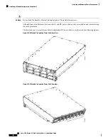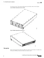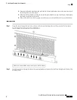
Do not install the power shelf in the chassis with AC or DC PMs, or alarm module installed in the power
shelf.
Note
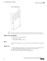
Required Tools and Equipment
• 6-in. long number 1 Phillips screwdriver
• 10-mm 6 pt. combination wrench
• Modular configuration AC or DC power shelf
• AC power shelf (Cisco product number CRS-16LCC-PSH-AC=), or
• DC power shelf (Cisco product number CRS-16LCC-PSH-DC=)
Steps
To install the modular configuration power shelf, perform the following steps:
SUMMARY STEPS
1.
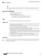
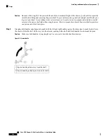
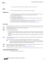
Using the 10-mm wrench, loosen the two bolts on the rear of the chassis that clamp the rear of the power
shelf to the chassis, as shown in this figure.
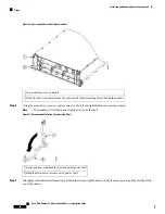
2.
Install the mounting blocks on the left and right sides of the chassis. The left side is shown in the next
figure. A second mounting block is located on the right side.
3.
Unscrew the ejector handles from the front face of the shelf, one on each side.
4.
Holding the power shelf underneath with one hand and steadying it with the other, lift the shelf up and
slide it partway into the power shelf slot on the front (PLIM) side of the chassis.
5.
Grasping both handles simultaneously, push both the left and right handles up in at the same time to push
the shelf into the chassis. Slide the shelf all the way into the chassis, pushing in the shelf until both handles
hook around the pins.
6.
Using the wrench, tighten the two bolts that attach the rear of the power shelf to the rear of the chassis.
7.
Using the screwdriver, turn the captive screws at the top of the left and right handles.
8.
Use the screwdriver to screw the shelf to the left and right mounting blocks through the handle holes.
There are four holes, two on each handle.
DETAILED STEPS
Step 1
Using the 10-mm wrench, loosen the two bolts on the rear of the chassis that clamp the rear of the power shelf to the
chassis, as shown in this figure.
Cisco CRS Routers 16-Slot Line Card Chassis Installation Guide
60
Installing and Removing Power Components
Required Tools and Equipment


