2-10
Cisco CRS Carrier Routing System 4-Slot Line Card Chassis Installation Guide
OL-10971-10
Chapter 2 Installing and Removing Power Components
DC Power Systems on the Cisco CRS 4-Slot Router
Note
When wiring the DC power shelf, be sure to attach the ground wire first. When removing the wiring, be
sure to remove the ground wire last. The ground wire must be attached with a torque value of 30 in-lb.
The power cables should also be attached with a torque value of 30 in-lb.
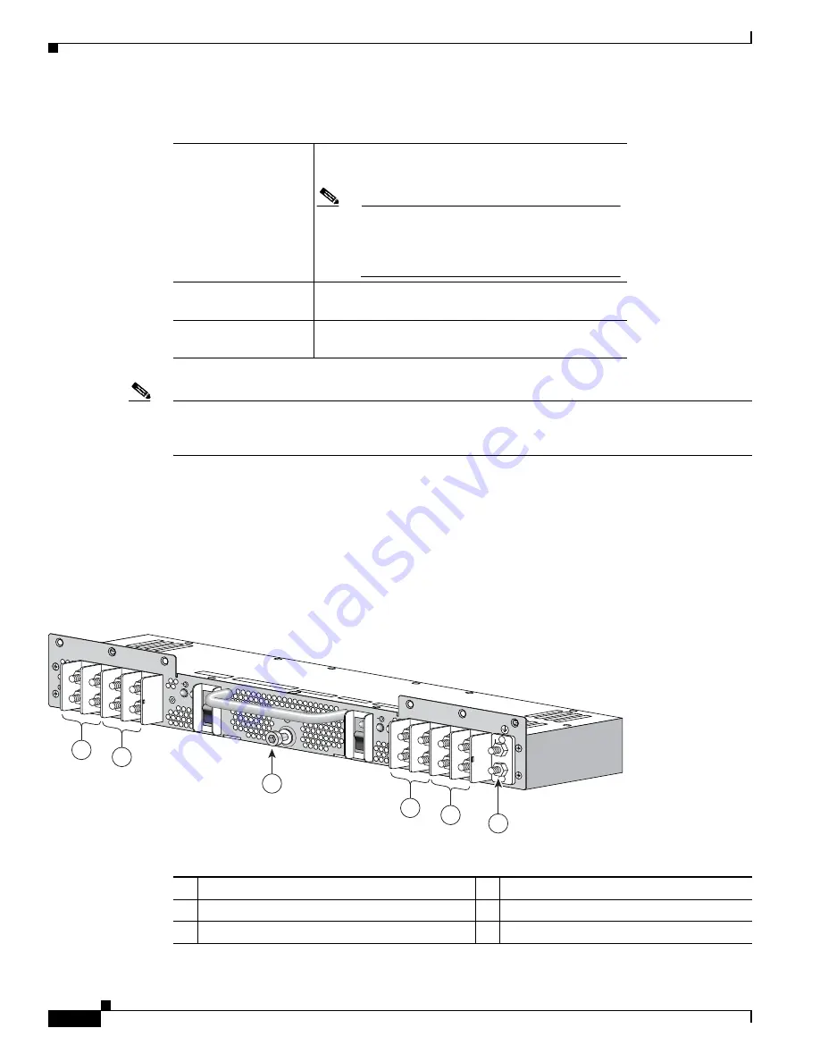
Wiring Block on the PIM
Each wiring block on the power input module (PIM) contains four sets of terminals, two positive and
two negative (see
Figure 2-10
). Each wiring block is covered by a plastic block cover that snaps onto
the wiring block and is secured by a screw to a torque value of 50 in.-lb.
You must remove the block cover before you work with the wires.
Figure 2-10
Power Input Module (PIM)
Table 2-2
DC Input Current and Voltage Information
Nominal input voltage
Supports –48 VDC and –60 VDC systems
(range: –40 to –72 VDC)
Note
The
turn-on
voltage of the DC power supplies
is –43.5 +/- 0.5 VDC. When a power supply is
powered on, it continues to operate down to an
input voltage of –40 VDC.
Input line current
50 A maximum at –48 VDC
40 A maximum at –60 VDC
Inrush current
60 A peak at –75 VDC
(maximum for 1 ms)
1
Power supply B1 wiring block
4
Power supply A1 wiring block
2
Power supply B0 wiring block
5
Power supply A0 wiring block
3
Power shelf coupling screw
6
Ground lug nuts
210614
B1
(RTN)
(-48V/-60V)
+
–
B0
B0
B1
ON
Side B
(RTN)
(-48V/-60
V)
+
–
A1
(RTN)
(-48V/-60
V)
+
–
A0
(RTN)
(-48V/-60
V)
+
–
A0
A1
ON
Side A
SIDE A
SIDE B
3
6
1
2
4
5


