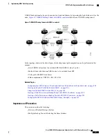
NNHOP backup tunnels also provide protection from link failures by bypassing the failed link as well as the
node.
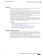
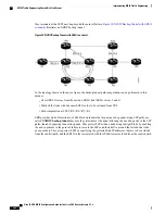
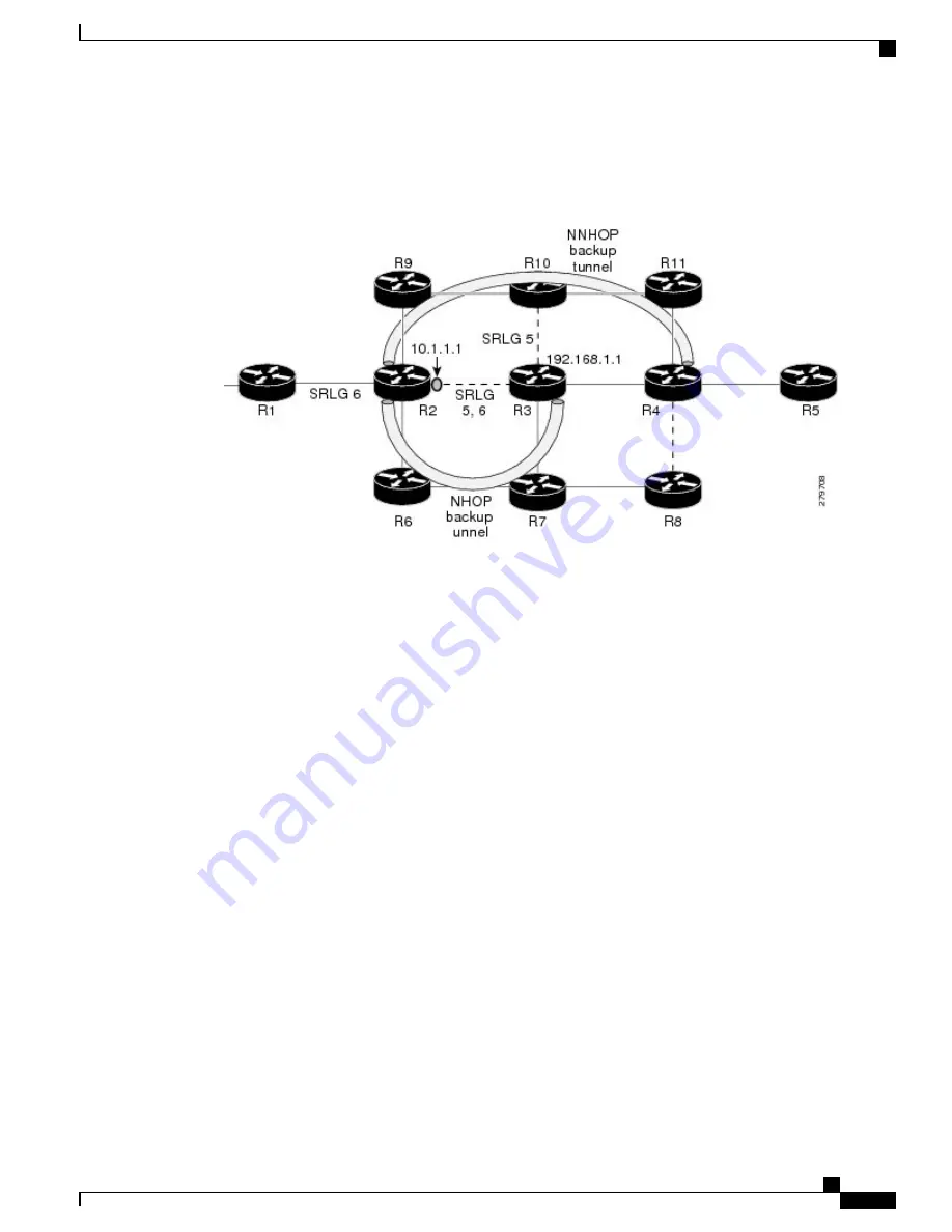
Figure 19: NNHOP Backup Tunnel with SRLG constraint
illustrates an NNHOP backup tunnel.
Figure 19: NNHOP Backup Tunnel with SRLG constraint
In the topology shown in the above figure, the backup tunnel path computation can be performed in this
manner:
•
Get all SRLG values from the exclude-SRLG link (SRLG values 5 and 6)
•
Mark all links with the same SRLG value to be excluded from SPF
•
Verify path with SRLG constraint
•
Path computation as CSPF R2->R9->R10->R4
Related Topics
Configuring the SRLG Values of Each Link that has a Shared Risk with Another Link, on page 294
Creating an Explicit Path With Exclude SRLG, on page 296
Using Explicit Path With Exclude SRLG, on page 298
Creating a Link Protection on Backup Tunnel with SRLG Constraint, on page 300
Creating a Node Protection on Backup Tunnel with SRLG Constraint, on page 303
Configure the MPLS-TE Shared Risk Link Groups: Example, on page 353
Importance of Protection
This section describes the following:
•
Delivery of Packets During a Failure
•
Multiple Backup Tunnels Protecting the Same Interface
Cisco IOS XR MPLS Configuration Guide for the Cisco CRS Router, Release 5.1.x
201
Implementing MPLS Traffic Engineering
MPLS Traffic Engineering Shared Risk Link Groups


