1-6
Installation Guide for Cisco Secure ACS Solution Engine 4.1
OL-9969-03
Chapter 1 Cisco Secure ACS Solution Engine Overview
ACS SE Hardware Description
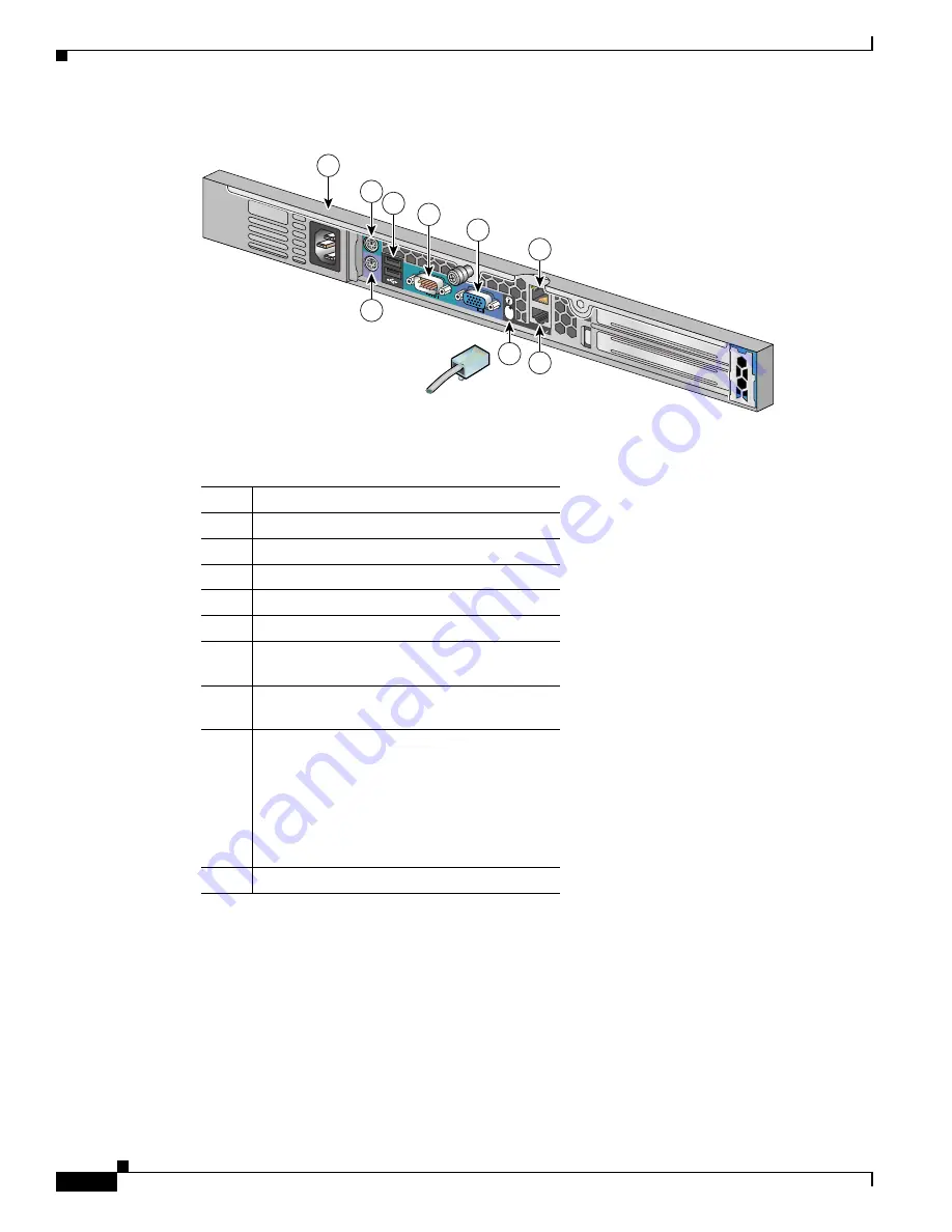
Figure 1-3
Back Panel Features for the Cisco 1113
The following table describes the callouts in
Figure 1-3
.
Serial Port
The integrated serial port on the back panel of the appliance uses a 9-pin, D-subminiature connector.
Serial Port Connector
If you reconfigure your hardware, you may need information regarding the pin number and signal for
the serial port connector.
Figure 1-4
illustrates the pin numbers for the serial port connector, and defines
the pin assignments and interface signals for the serial port connector. (Pin numbering proceeds bottom
to top and right to left, as illustrated.)
149999
1 2
2
1
Gb
1
9
8
7
2
3
4
5
6
No.
Description
1
AC power receptacle
2
Mouse connector (not supported). Do not use.
3
USB connectors (not supported). Do not use.
4
Serial connector (see
Figure 1-3
)
5
Video connector (not supported). Do not use.
6
RJ-45 Fast Ethernet connector with
10/100/1000-Mbit/s operation for NIC 2
7
RJ-45 Fast Ethernet connector with
10/100/1000-Mbit/s operation for NIC 1
8
Unit Identification Button and LED. When the
Unit Identification Button on the front panel is
pressed, this causes the Unit Identification
Button on the back panel to flash blue. To turn
off the Unit Identification indicator on the
back panel, push the Unit Identification
button.
9
Keyboard connector


