Statement 1007
—
TN and IT Power Systems
This equipment has been designed for connection to TN and IT power systems.
Warning
Statement 1002
—
DC Power Supply
When stranded wiring is required, use approved wiring terminations, such as closed-loop or spade-type
with upturned lugs. These terminations should be the appropriate size for the wires and should clamp both
the insulation and conductor.
Warning
Statement 1003
—
DC Power Disconnection
Before performing any of the following procedures, ensure that power is removed from the DC circuit.
Warning
Statement 1046
—
Installing or Replacing the Unit
When installing or replacing the unit, the ground connection must always be made first and disconnected
last.
Warning
Statement 1022
—
Disconnect Device
A readily accessible two-poled disconnect device must be incorporated in the fixed wiring.
Warning
Statement 1025
—
Use Copper Conductors Only
Use copper conductors only.
Warning
After rack mounting the Firepower 2100 series security appliance, follow these steps to connect cables, turn
on power, and verify connectivity.
Step 1
Connect the console port.
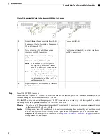
Using a serial console cable, connect a computer or terminal server to the RJ-45 serial console port (baud rate is 9600)
so that you can use the Firepower Device Manager or the CLI (and then continue configuration using the Firepower
Management Center ) to initially set up the Firepower 2100.
Step 2
Connect the management interface.
Install the management cable that was provided in the Firepower 2100 accessory kit in the Management port,
Cisco Firepower 2100 Series Hardware Installation Guide
40
Mount and Connect
Connect Cables, Turn on Power, and Verify Connectivity


