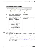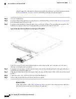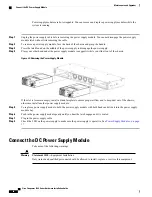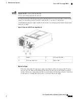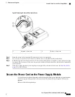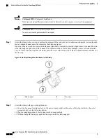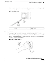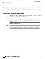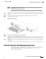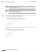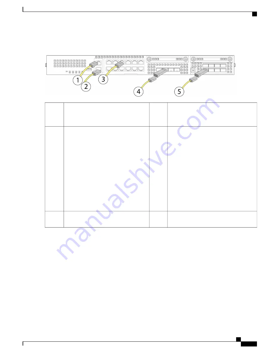
Figure 19: Connecting the Cables to the Firepower 2100 Security Appliance
Console port (RJ-45)
2
Gigabit Ethernet Management interface (RJ-45)
Management 0 (also referred to as Management
1/1 and Diagnostic 1/1)
1
Four fixed-port Gigabit Ethernet data interfaces
for SFP+ transceivers
4
Twelve fixed-port Gigabit Ethernet data
interfaces for SFP+ transceivers
Flip the SFP+ over to connect in the upper
ports.
Ethernet 1/1 through Ethernet 1/12
The Ethernet 1/1 (WAN) port is
configured by default for internet
access. Connect your DHCP enabled
cable modem (internet) to this port.
Note
The Ethernet 1/2 (inside) port is
configured by default for inside
access. Firepower 2100 bootstrapping
is only supported on Ethernet 1/2 or
on Management 0.
Note
3
Eight fixed port Gigabit Ethernet data interfaces
for SPF+ transceivers.
5
Step 3
Install the SFP/SFP+ transceivers.
Install SFP/SFP+/ transceivers in the Ethernet network interfaces in the fixed ports or in the network modules you have
installed taking care not to touch the contacts in the rear.
Flip the SFP+ over to connect in the upper ports. The SFP+ connects in the normal way in the lower ports. The sockets
on the upper row face up and the sockets on the lower row face down.
Do not force an SFP transceiver into a socket. This can jam the transceiver and can cause permanent damage
to the transceiver, the chassis, or both.
Warning
Although non-Cisco SFPs are allowed, we do not recommend using them because they have not been tested
and validated by Cisco. Cisco TAC may refuse support for any interoperability problems that result from
using an untested third-party SFP transceiver. See
Supported SFP/SFP+ Transceivers, on page 20
for a list
of supported Cisco transceivers.
Caution
Cisco Firepower 2100 Series Hardware Installation Guide
41
Mount and Connect
Connect Cables, Turn on Power, and Verify Connectivity

