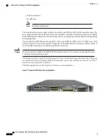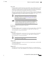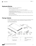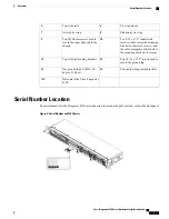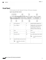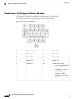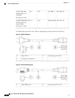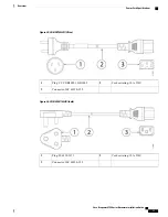
Ethernet
X
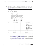
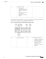
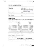
/1 (top port)
Ethernet
X
/2 (bottom port)
Ports 1 and 2 are paired together to
form a hardware bypass pair.
4
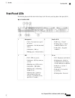
Bypass LEDs B1 through B3
•
Solid green
–
In Standby
mode.
•
Blinking amber
–
Port is in
hardware bypass mode,
failure event.
•
Solid amber
–
Port is in
hardware bypass mode,
forced.
3
Ethernet
X
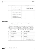
/5 (top port)
Ethernet
X
/6 (bottom port)
Ports 5 and 6 are paired together to
form a hardware bypass pair.
6
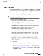
Ethernet
X
/3 (top port)
Ethernet
X
/4 (bottom port)
Ports 3 and 4 are paired together
to form a hardware bypass pair.
5
1G SX/10G SR/10G LR Network Module Insertion Loss
The 1G SX /10G SR/10G LR network module has the following insertion loss measurements. Insertion loss
measurements help you to troubleshoot the network by verifying cable installation and performance.
Table 1: 1G SX Network Module (FPR-NM-6X1SX-F)
Maximum
Typical
Operating Mode
1.4 dB
1.7 dB
0.9 dB
1.2 dB
Normal
Hardware bypass
Insertion loss
Cable Distance
Half the distance
specified by the
IEEE standard.
Note
Modal Bandwidth
(MHz/km
Core Diameter (microns)
110 m
137 m
250 m
275 m
500 m
160 (FDDI)
200(OM1)
400
500 (OM2)
2000 (OM3)
62.5
62.5
50
50
50
Cable and operating
distance
Table 2: 10G SR Network Module (FPR-NM-6X10SR-F)
Maximum
Typical
Operating Mode
Cisco Firepower 4100 Series Hardware Installation Guide
16
Overview
Hardware Bypass (FTW) Network Modules

