


1-10 Cisco 12012 Gigabit Switch Router Installation and Configuration Guide
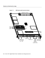
Physical and Functional Overviews
NVRAM
The system configuration, software configuration register settings, and environmental
monitoring logs are contained in the 512-KB NVRAM, which is backed up with built-in
lithium batteries that retain the contents for a minimum of five years. NVRAM is not user
configurable or field-upgradeable.
Caution
Before you replace the GRP in the system, back up the running configuration to
a Trivial File Transfer Protocol (TFTP) file server or an installed Flash memory card so you
can retrieve it later. If the configuration is not saved, the entire configuration will be
lost—inside the NVRAM on the removed GRP—and you will have to reenter the entire
configuration manually. This procedure is not necessary if you are temporarily removing a
GRP; lithium batteries retain the configuration in memory until you replace the GRP in the
system.
Flash Memory
Both the onboard and PCMCIA card-based Flash memory allow you to remotely load and
store multiple Cisco IOS software and microcode images. You can download a new image
over the network or from a local server and then add the new image to Flash memory or
replace the existing files. You can then boot the routers either manually or automatically
from any of the stored images. Flash memory also functions as a TFTP server to allow other
servers to boot remotely from stored images or to copy them into their own Flash memory.
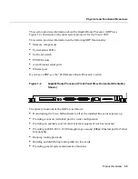
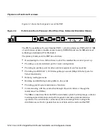
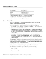
System Status LEDs
This section describes the two types of system status LEDs used on the GRP: LED
indicators and alphanumeric LED displays.
•
The GRP has the following eight LED indicators:
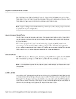
— Two PCMCIA activity LEDs (one per PCMCIA slot): these LEDs light when the
slot is accessed. The LEDs receive power from the switched slot voltage.
— Four RJ-45 Ethernet port LEDs: these LEDs are used in conjunction with the RJ-45
Ethernet connector. When the MII Ethernet port is in use, the LEDs are disabled.
The LEDs indicate link activity, collision detection, data transmission, and data
reception.
Summary of Contents for Gigabit Switch Router Cisco 12012
Page 4: ......
Page 12: ...xii Cisco 12012 Gigabit Switch Router Installation and Configuration Guide ...
Page 16: ...xvi Cisco 12012 Gigabit Switch Router Installation and Configuration Guide ...
Page 96: ...2 26 Cisco 12012 Gigabit Switch Router Installation and Configuration Guide Site Log ...
Page 310: ...14 Cisco 12012 Gigabit Switch Router Installation and Configuration Guide ...


