B-24
Cisco IE 3000 Switch Hardware Installation Guide
Appendix B Installation In a Hazardous Environment
Verifying Switch Operation
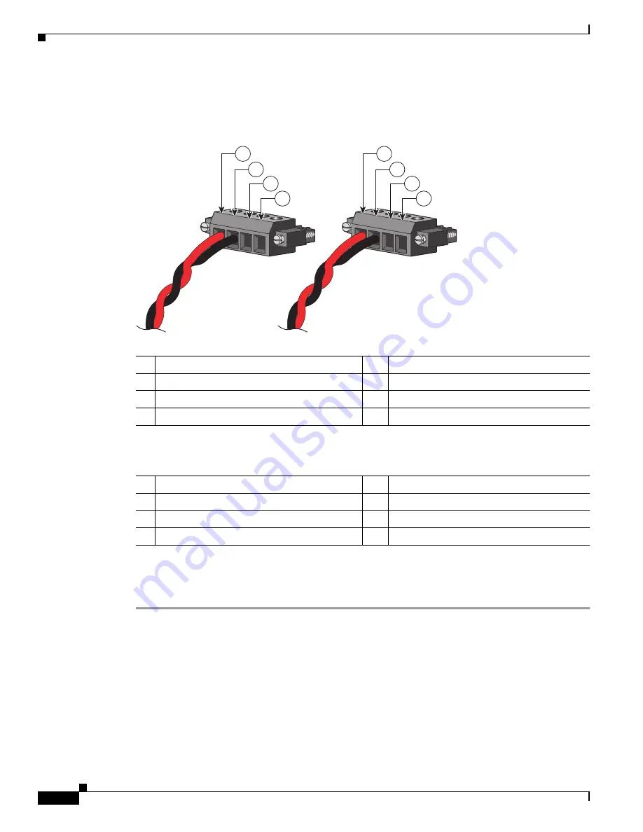
shows the completed DC-input wiring on a power and relay connector for a primary power
source and an optional secondary power source.
Figure B-16
Completed DC Power Connections on the Power and Relay Connector
If your power source is –48 VDC, this table descibes the your wiring connections for
.
Step 8
(Optional) If you plan to connect external alarm devices to the alarm relays and the switch is already
installed, go to the
“Wiring the External Alarms” section on page B-41
. Otherwise, go to the
Switch Operation” section on page B-15
1
Power source A positive connection
5
Power source B positive connection
2
Power source A return connection
6
Power source B return connection
3
External device 1, relay wire connection
7
External device 2, relay wire connection
4
External device 1, relay wire connection
8
External device 2, relay wire connection
201
8
1
8
RT A
V
A
RT A
V
A
1
2
3
4
5
6
7
8
1
Power source A return connection
5
Power source B return connection
2
Power source A –48 VDC connection
6
Power source B –48 VDC connection
3
External device 1, relay wire connection
7
External device 2, relay wire connection
4
External device 1, relay wire connection
8
External device 2, relay wire connection


