2-36
Cisco IE 3000 Switch Hardware Installation Guide
Chapter 2 Switch Installation
Connecting Power and Alarm Circuits
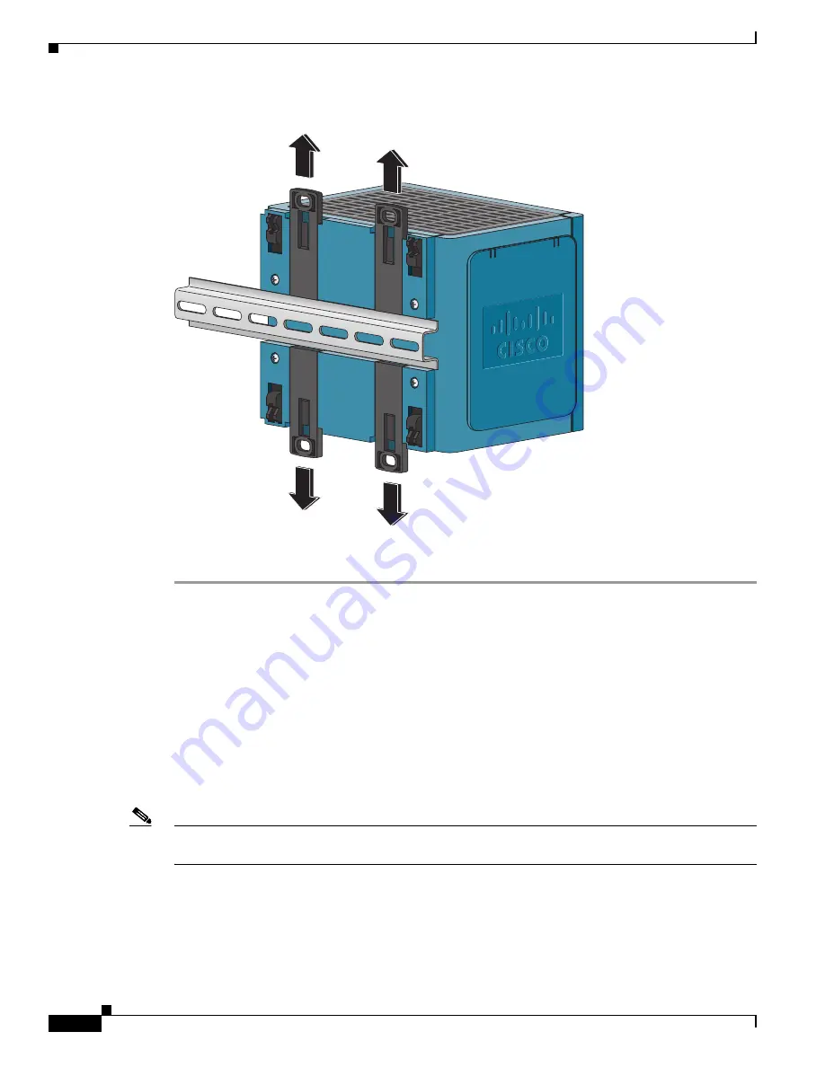
Figure 2-27
Removing the Switch from the DIN Rail
Step 4
Remove the switch from the DIN rail.
Connecting Power and Alarm Circuits
After the switch is installed, you are ready to connect the DC power and alarm relays.
•
Wiring the Protective Ground and DC Power, page 2-36
•
Wiring the External Alarms, page 2-37
Wiring the Protective Ground and DC Power
Note
The switch can use either a dual or single positive DC input (24V/48V), or a single negative DC input
(-24V/-48V). Dual negative DC inputs are not supported.
For instructions on grounding the switch and connecting the DC power, see the
Protective Ground and DC Power” section on page 2-15
.
For instructions on using a power converter for DC power, see the
“Connecting the Switch to the Power
Converter” section on page 2-48
201850


