2-51
Cisco IE 3000 Switch Hardware Installation Guide
Chapter 2 Switch Installation
Connecting the Switch to the Power Converter
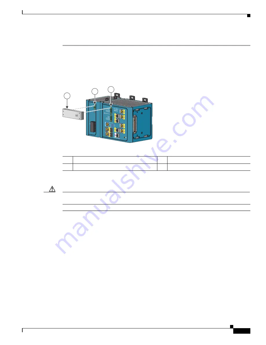
Follow these steps to connect DC power from the power converter to the switch module.
Step 1
Locate the DC power clip in the power converter accessory kit.
Step 2
Position the power clip so that the two-pin connector is over the power converter and the four-pin
connector is over the switch Pwr A connector, and then slide the power clip into these two connectors.
See
.
Figure 2-41
Connecting Wires to the Power Converter DC Output Terminal Block
Step 3
Use a ratcheting torque flathead screwdriver to tighten the captive screw to 2.2 in-lb (0.25 Nm).
Caution
Do not over-torque the power and relay connector captive screws. The torque should not exceed 2.2 in-lb
(0.25 Nm).
Connecting the Power Converter to an AC Power Source
These sections describe the steps required to connect the power converter to an AC power source:
•
Preparing the AC Power Cord, page 2-51
•
Connecting the AC Power Cord to the Power Converter, page 2-52
Preparing the AC Power Cord
To connect the power converter to an AC power source, you need an AC power cord. Power cord
connector types and standards vary by country. Power-cord wiring color codes also vary by country. You
must to have a qualified electrician select, prepare, and install the appropriate power cord to the power
supply.
1
DC power clip
3
Four-pin connector on the switch
2
Two-pin connector on the power convertor
DC OK
24V , 2
.1A
Rtn Out
(-)
Pwr Out (+)
125-250V
, 1.25A M
AX
100-240V~
, 50-60Hz/
N /
L /
202298
1
5
2
6
3
7
4
8
C
O
NSOLE
1
2
1
2
3


