Software Configuration of ATM ISE Line Cards for Cisco 12000 Series Routers
How to Configure AToM VCs on the 4-Port ATM ISE Line Card
72
Cisco IOS Release 12.0(27)S
Attaching a Service Policy to a PVC
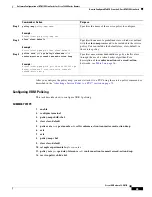
After you define a service policy with the desired QoS configuration, you must attach it to a PVC as
described in this task.
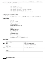
SUMMARY STEPS
1.
enable
2.
configure
terminal
3.
interface atm
slot/port
4.
atm clock internal
5.
pvc
vpi/vci
l2transport
6.
encapsulation aal0
7.
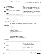
xconnect
peer-router-id vcid
encapsulation mpls
8.
service-policy input
policy-map-name
DETAILED STEPS
Command or Action
Purpose
Step 1
enable
Example:
Router> enable
Enables privileged EXEC mode.
•
Enter your password if prompted.
Step 2
configure
terminal
Example:
Router# configure terminal
Enters global configuration mode.
Step 3
interface atm
slot
/
port
Example:
Router(config)# interface atm1/0
Specifies an ATM interface to configure.
Step 4
atm clock internal
Example:
Router(config)# atm clock internal
Causes the ATM interface to generate the transmit clock
internally.
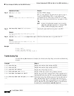
Step 5
pvc
vpi/vci
l2transport
Example:
Router(config-if)#
pvc 1/200 l2transport
Assigns a virtual path identifier (VPI) and virtual circuit
identifier (VCI). The
l2transport
keyword indicates that
the PVC is a switched PVC and not a terminated PVC.
Step 6
encapsulation aal0
Example:
Router(config-atm-l2trans-pvc)# encapsulation
aal0
For ATM Cell Relay, this command specifies raw cell
encapsulation for the interface. Make sure you specify the
same encapsulation type on the PE and CE routers.


