background image

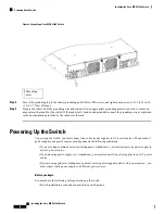
Figure 3: Grounding a Cisco MDS 9396S Switch

Grounding
point

1

Step 3

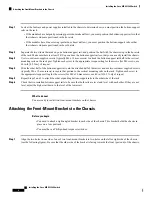
Secure the grounding lug to the chassis grounding pad with two M4 screws, and tighten each screw to 11.5 to 15 in-lb
(1.3 to 1.7 N·m) of torque.

Step 4

Prepare the other end of the grounding wire and connect it to an appropriate grounding point in your site to ensure an
adequate earth ground for the switch. If the rack is fully bonded and grounded, connect the grounding wire as explained
in the documentation provided by the vendor for the rack.

Powering Up the Switch

To power up the switch, you must connect one or two power supplies to AC power sources. The number of
power supplies and power sources used depends on the following conditions:

• If you are using combined power (not using power redundancy), you must connect one power supply to

one AC power source.

• If you are using power supply (n+1) redundancy, you must connect two power supplies to one AC power

source.

• If you are using grid (n+n) redundancy, you must use two power supplies and two AC power sources—you

must connect each power supply to a different power source.

Before you begin

You must have the following before powering up the switch:

• Switch installed in a rack and connected to an earth ground

Installing the Cisco MDS 9396S Switch

10

Installing the Cisco MDS 9396S Switch

Powering Up the Switch

Summary of Contents for MDS 9396S

Page 1: ...vided at the end of each warning to locate its translation in the translated safety warnings that accompanied this device Statement 1071 SAVE THESE INSTRUCTIONS Warning This unit is intended for installation in restricted access areas A restricted access area can be accessed only through the use of a special tool lock and key or other means of security Statement 1017 Warning Only trained and quali...

Page 2: ...e Cisco MDS 9000 Family Telco and EIA Shelf Bracket section The Telco and EIA Shelf Bracket Kit is optional and is not provided with the switch To order the kit contact your switch provider Note Installation Guidelines Follow these guidelines when installing the Cisco MDS 9396S Switch Plan your site configuration and prepare the site before installing the switch The recommended site planning tasks...

Page 3: ...echnology These UPS types can become unstable with systems such as the Cisco MDS 9000 Family which can have substantial current draw fluctuations because of fluctuating data traffic patterns Caution Ensure that circuits are sized according to local and national codes For North America the 300 W power supplies require a 20 A circuit If you are using a 200 or 240 VAC power source in North America th...

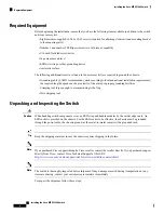
Page 4: ...e stripping tool Unpacking and Inspecting the Switch When handling switch components wear an ESD strap and handle modules by the carrier edges only An ESD socket is provided on the chassis For the ESD socket to be effective the chassis must be grounded through the power cable the chassis ground or the metal to metal contact with a grounded rack Caution Keep the shipping container in case the chass...

Page 5: ... on the Rack The switch chassis that you are installing ships with two adjustable bottom support rails that you can attach to a four post rack to hold the chassis Each of these bottom support rails has two pieces one that slides into the other so that you can adjust them to fit racks with front and rear mounting posts that are spaced less than 36 inches 91 cm On each bottom support rail the rail h...

Page 6: ... of the rail set and use two customer supplied screws typically M6 x 10 mm screws to secure that portion to the vertical mounting rails on the rack Tighten each screw to the appropriate torque setting for the screws for M6 x 10 mm screws use 40 in lb 4 5 N m of torque Step 5 Repeat Steps 2 and 3 to attach the other expanding bottom support rails to the other side of the rack Step 6 Check the two i...

Page 7: ...o the chassis stops at the end of the rails and so that the front mount brackets on the chassis come into contact with the front mount rails on the rack Make sure that the four post rack is properly installed and secured to the concrete floor Make sure that the bottom support rails are installed so that the power supplies and fan trays will be in the appropriate aisle The color of the stripe on fa...

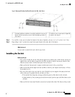
Page 8: ...ails toward the sides of the chassis so that the chassis stops can go inside the chassis and hold it in place on the rack Figure 2 Sliding the Chassis onto the Bottom Support Rails Customer supplied rack mount screw M6 x 10 mm screw or other appropriate screw used to secure each side of the chassis to the rack 3 Slide the fan tray end of the chassis onto the bottom support rails so that the chassi...

Page 9: ...holed standard barrel lug that supports up to 6 AWG wire This lug is supplied with the accessory kit Grounding screws Two M4 x 8 mm pan head screws These screws are shipped with the accessory kit Grounding wire Not supplied with the accessory kit This wire should be sized to meet local and national installation requirements Depending on the power supply and system a 12 AWG to 6 AWG copper conducto...

Page 10: ... must connect one or two power supplies to AC power sources The number of power supplies and power sources used depends on the following conditions If you are using combined power not using power redundancy you must connect one power supply to one AC power source If you are using power supply n 1 redundancy you must connect two power supplies to one AC power source If you are using grid n n redund...

Page 11: ... green If the LED is off check the AC power source circuit breaker to be sure that it is turned on Step 3 If you are using the grid n n redundancy you must connect the second power supply as follows a Using the recommended power cable for your country or region see the Supported Power Cords and Plugs section connect the C19 plug on the power cable to the power receptacle on the second power supply...

Page 12: ...96S Switch Removing and Installing AC Power Supplies This section provides instructions for removing and installing the AC power supplies for the Cisco MDS 9396S switch Removing Power Supplies To remove an AC power supply follow these steps Step 1 Turn the power switch to the off 0 position on the power supply that you are removing Step 2 Disconnect the power cord from the power source Step 3 Loos...

Page 13: ...switch Removing a Fan Module The fan module is designed to be removed and replaced while the system is operating without presenting an electrical hazard or damaging the system The Cisco MDS 9000 Family has internal temperature sensors that can shut down the system if the temperature at different points within the chassis exceed certain safety thresholds To accurately monitor the system temperature...

Page 14: ...eplate is flush with the switch back panel Step 2 Verify that the fan module LED is green If the LED is orange then one fan has failed in this fan module if the LED is red then both fans have failed in this fan module Step 3 Contact your customer service representative for assistance if after several attempts the fans do not operate or you experience trouble with the installation If you purchased ...

Reviews: