3-3
Cisco MWR 1941-DC Mobile Wireless Edge Router Software Configuration Guide
OL-11503-01
Chapter 3 First-Time Configuration
Using the Setup Command Facility
Interface (port) numbers begin at 0 for each interface type, and continue from right to left.
•
The two built-in Ethernet 10/100 interfaces are Fast Ethernet 0/0 and Fast Ethernet 0/1.
•
The slot number for all VWIC interfaces in the built-in VWIC slot is always 0. (The W0, W1, and
W2 slot designations are for physical slot identification only.) Interfaces in the VWICs are
numbered from right to left, starting with 0/0 for each interface type, regardless of the physical
VWIC slot in which the VWICs are installed.
For example, if you have a VWIC in two of the VWIC slots (W0 and W1), then the interfaces are:
–
Serial 0/0 and Serial 0/1 in physical slot W0
–
Serial 0/2 and Serial 0/3 in physical slot W1
However, if you install a VWIC in physical slot W1 (leaving slot W0 empty), the interfaces in slot
W1 are Serial 0/0 and Serial 0/1. If you then add a VWIC to slot W0, the interface numbering will
shift. The configuration that you created for interfaces Serial 0/0 and Serial 0/1 will now be applied
to the VWIC in slot W0 and you will need to create a new configuration for the interfaces that you
previously configured on W1 (which will now be Serial 0/2 and Serial 0/3).
•
The slot number of WIC/VWIC interfaces installed in slot 1 using a WAN network module is always
1 and the interfaces are always numbered from the right to left.
•
The slot number for all network module interfaces is always 1 and the interfaces are always
numbered from right to left starting with 1/0.
Before Starting Your Router
Before you power ON your router and begin to use the setup command facility, make sure you follow
these steps:
Step 1
Set up the hardware and connect the console and network cables as described in the
Cisco MWR 1941-DC Router Hardware Installation Guide
.
Step 2
Configure your PC terminal emulation program for 9600 baud, 8 data bits, no parity, and 1 stop bit.
Using the Setup Command Facility
The setup command facility displays from your PC terminal emulation program window.
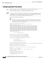
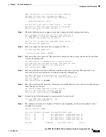
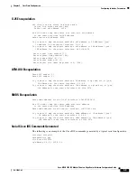
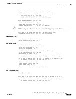
To create a basic configuration for your router, do the following:
•
Complete the steps in the
“Configuring Global Parameters” section on page 3-4
.
•
Complete the steps in the
“Configuring Interface Parameters” section on page 3-6
.
•
Complete the steps in the
“Completing the Configuration” section on page 3-12
.
Note
If you make a mistake while using the setup command facility, you can exit and run the facility again.
Press
Ctrl-c
, and type
setup
at the enable mode prompt (
1900#
).
Summary of Contents for MWR 1941-DC - 1941 Mobile Wireless Router
Page 49: ...P A R T 1 Implementing the MWR 1941 DC Router in an IP RAN ...
Page 50: ......
Page 107: ...P A R T 2 Implementing the MWR 1941 DC Router in a Cell Site DCN ...
Page 108: ......


