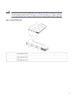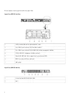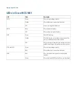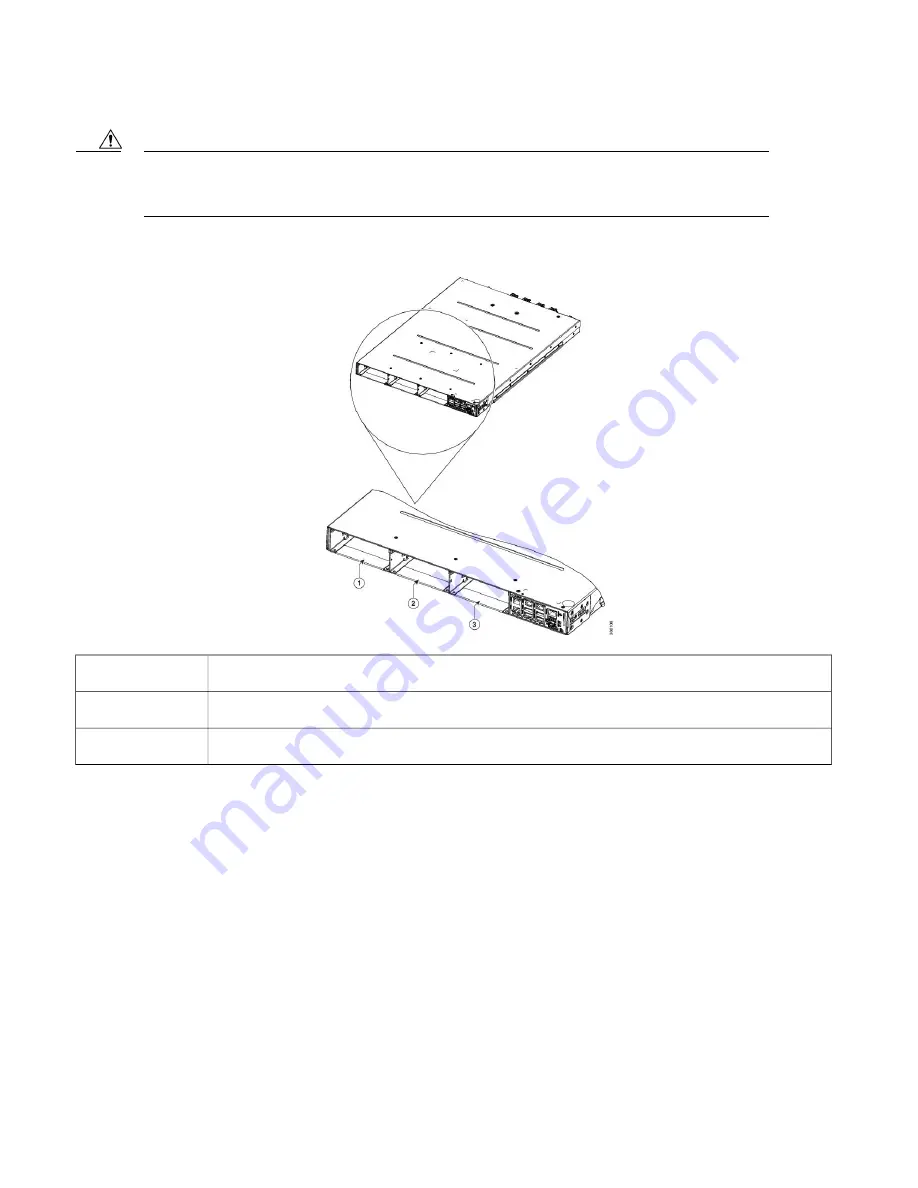
The empty slots must be inserted with the filler optical modules or filler PSUs as appropriate to guarantee
safety and system cooling compliance. See
Figure 1: Cisco NCS 1001 Front View, on page 3
and
3: Cisco NCS 1001 Rear View, on page 4
to identify the slots for optical modules and PSUs respectively.
Caution
Figure 1: Cisco NCS 1001 Front View
Optical Module Slot 1
1
Optical Module Slot 2
2
Optical Module Slot 3
3
3
Summary of Contents for NCS 1001
Page 1: ...Quick Start Guide for Cisco NCS 1001 ...
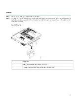
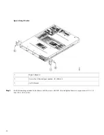
Page 25: ...Left side four post slide assembly 1 25 ...
Page 30: ...30 ...
Page 34: ...34 ...


