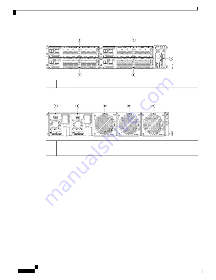
Figure 1: NCS 1004 Front View
Controller
2
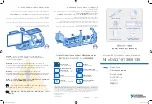
The slots for the PSUs and fan units are indicated in the following figure.
Figure 2: NCS 1004 Rear View
Power Supply Units (Slots 0 and 1)
1
Fan Units (Slots 0,1,2)
2
Both the power supply modules should be AC or DC. Mixed configuration is not allowed.
Cisco NCS 1004 has a front to back airflow scheme. The air inlet is at the front side of the chassis and the
exhaust is on the rear side. Ensure that the airflow is not obstructed or impeded by any object as it may lead
to reduced airflow in the system, causing components to operate at a higher temperature.
Hardware Installation Guide for Cisco NCS 1004
2
Cisco NCS 1004 Overview
Cisco NCS 1004 Overview


