background image

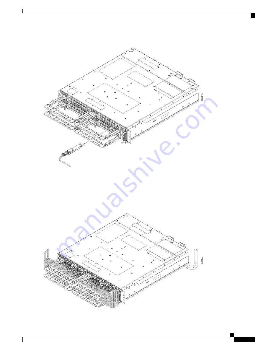
Figure 48: Inserting QSFP Pluggable (1.2T Line Card)

The pull tabs of the pluggables must always face down for top rows; the pull tabs of the pluggables must always
face up for bottom rows.

Caution

Do not forcibly push the pluggable into the slot, this might damage the pluggable and/or the slot.

Step 3

Route the cables emerging from the pluggables using the fiber management bracket as shown in the following figure.

Figure 49: Fiber Management Bracket with fibers from Pluggables (1.2T Line Card)

Hardware Installation Guide for Cisco NCS 1004

51

Install Cisco NCS 1004 Modules

Install Pluggables

Summary of Contents for NCS 1004

Page 1: ...for Cisco NCS 1004 First Published 2019 08 30 Last Modified 2020 04 21 Americas Headquarters Cisco Systems Inc 170 West Tasman Drive San Jose CA 95134 1706 USA http www cisco com Tel 408 526 4000 800 553 NETS 6387 Fax 408 527 0883 ...

Page 2: ...RSE OF DEALING USAGE OR TRADE PRACTICE IN NO EVENT SHALL CISCO OR ITS SUPPLIERS BE LIABLE FOR ANY INDIRECT SPECIAL CONSEQUENTIAL OR INCIDENTAL DAMAGES INCLUDING WITHOUT LIMITATION LOST PROFITS OR LOSS OR DAMAGE TO DATA ARISING OUT OF THE USE OR INABILITY TO USE THIS MANUAL EVEN IF CISCO OR ITS SUPPLIERS HAVE BEEN ADVISED OF THE POSSIBILITY OF SUCH DAMAGES Any Internet Protocol IP addresses and pho...

Page 3: ...co NCS 1004 has the following modules Removable controller Two replaceable power supply units PSU Three replaceable fan units Four line card slots For more information about the Cisco NCS 1004 chassis the NCS1K4 1 2T K9 or 1 2 Tbps C band line card see Cisco NCS 1004 datasheet 1 2T refers to the NCS1K4 1 2T K9 C band line card Note The controller is on the front side The PSUs and the fan units are...

Page 4: ...AC or DC Mixed configuration is not allowed Cisco NCS 1004 has a front to back airflow scheme The air inlet is at the front side of the chassis and the exhaust is on the rear side Ensure that the airflow is not obstructed or impeded by any object as it may lead to reduced airflow in the system causing components to operate at a higher temperature Hardware Installation Guide for Cisco NCS 1004 2 Ci...

Page 5: ...duct label is shown in the following figure Figure 4 Class 1M Laser Product Label Supported Pluggables The following pluggables are supported on NCS 1004 QSFP 100G SR4 S QSFP 100G CWDM4 S Hardware Installation Guide for Cisco NCS 1004 3 Cisco NCS 1004 Overview Supported Pluggables ...

Page 6: ...00G AOC 1M QSFP 100G AOC 3M QSFP 100G AOC 10M QSFP 100G LR4 S QSFP 100G CU1M QSFP 100G CU2M QSFP 100G CU3M QSFP 100G CU5M QSFP28 FR Hardware Installation Guide for Cisco NCS 1004 4 Cisco NCS 1004 Overview Supported Pluggables ...

Page 7: ...ion and Removal on page 6 Safety with Electricity on page 7 Power Connection Guidelines on page 7 Safety Precaution for Energy Hazard on page 8 Safety Precaution for Laser Radiation on page 8 Prevent Electrostatic Discharge Damage on page 9 Standard Warning Statements This unit is intended for installation in restricted access areas A restricted access area can be accessed only by using a special ...

Page 8: ... scarf and sleeves Operate Cisco equipment safely by using it in accordance with its electrical ratings and product usage instructions Do not work alone if potentially hazardous conditions exist Ensure that the installation of the router is in compliance with national and local electrical codes in the United States National Fire Protection Association NFPA 70 United States National Electrical Code...

Page 9: ...alled ground conductor Contact the appropriate electrical inspection authority or an electrician if you are uncertain that suitable grounding is available Statement 1024 Warning This unit may have more than one power supply connection All connections must be removed to de energize the unit Statement 1028 Warning When installing or replacing the unit ensure the ground connection first and disconnec...

Page 10: ... Warning Safety Precaution for Energy Hazard Do not reach into a vacant slot when installing or removing a module Exposed circuitry is an energy hazard Statement 206 Warning The Cisco NCS 1004 can be configured for a DC power source Do not touch terminals with body parts or conductive objects while they are energized Safety Precaution for Laser Radiation Cisco NCS 1004 is classified as Hazard Leve...

Page 11: ...n procedures Ensure that the device chassis is electrically connected to earth ground Wear an ESD preventive wrist strap ensuring that it makes good skin contact Handle components by only their handles or edges do not touch the printed circuit boards or connectors Avoid contact between the printed circuit boards and clothing The wrist strap only protects components from ESD voltages on the body ES...

Page 12: ...Hardware Installation Guide for Cisco NCS 1004 10 Safety Guidelines Prevent Electrostatic Discharge Damage ...

Page 13: ...card or filler cards preinstalled in the chassis The controller and the three fan units are also preinstalled The other items available in the same package with the chassis are Accessory kit that has all the installation hardware Two PSUs AC or DC Installation of PSUs is discussed in the Install Cisco NCS 1004 Modules chapter AC chassis while ordering for an AC chassis select the power cable Based...

Page 14: ...e 6 90 degree Cable CEE 7 7 Figure 7 90 degree Cable NEMA L6 20P Figure 8 Straight Cable NEMA L6 20P Hardware Installation Guide for Cisco NCS 1004 12 Prepare to Install Cisco NCS 1004 Shipping and Receiving ...

Page 15: ...ou order for a DC chassis you get four power lugs for each PSU a pair of 90 degree and a pair of 180 degree lugs 180 degree lugs are used for ETSI racks to maintain a footprint of 600 mm Figure 10 DC Power Cable Lug 180 degree Hardware Installation Guide for Cisco NCS 1004 13 Prepare to Install Cisco NCS 1004 Shipping and Receiving ...

Page 16: ...of 600 mm Note Table 2 Specifications of Breakout Cables Overall Length in m MPN CPN PID 05 plus or minus 0 30 BCJ7F3FM005CSO008 72 101758 01 ONS 4X10 MMCBL 5 10 plus or minus 0 30 BCJ7F3FM010CSO008 72 101759 01 ONS 4X10 MMCBL 10 Hardware Installation Guide for Cisco NCS 1004 14 Prepare to Install Cisco NCS 1004 Shipping and Receiving ...

Page 17: ...f the filler cards Each line card ordered as a spare item is shipped separately and the extra fiber management bracket for the line card is available in the line card package Only the accessory kit is available with the chassis in the same package You must order all the other modules fan units controller PSUs separately For installation procedures of the modules see Install Cisco NCS 1004 Modules ...

Page 18: ...ep 2 Remove accessories and foam inserts from the box The box contains Cisco NCS 1004 and other items needed for installation Step 3 To remove the chassis from the packaging grasp the side of the chassis and lift it out of the box Use these lifting guidelines to avoid injury to yourself or damage to the equipment Do not lift equipment alone have another person help you to lift the equipment Hardwa...

Page 19: ...t equipment bend at the knees not at the waist to reduce the strain on your lower back muscles Step 4 Verify the following The Cisco NCS 1004 is not damaged Check for a scratch bend discoloration or deformation on the Cisco NCS 1004 chassis The modules that are shipped with the chassis or separately are not damaged Step 5 If there is any damage to the chassis or the modules call your Cisco sales e...

Page 20: ...Hardware Installation Guide for Cisco NCS 1004 18 Prepare to Install Cisco NCS 1004 Unpack and Verify Cisco NCS 1004 ...

Page 21: ... Install NCS 1004 on an EIA ANSI ETSI Rack on page 21 Stacking NCS 1004 on page 33 General Power and Grounding Requirements on page 35 Power Supply on page 37 Rack Compatibility This section provides rack compatibility details for the Cisco NCS 1004 Figure 16 Four Post Rack Type Hardware Installation Guide for Cisco NCS 1004 19 ...

Page 22: ...Figure 17 Four Post Rack Type Figure 18 Two Post Rack Type Hardware Installation Guide for Cisco NCS 1004 20 Install Cisco NCS 1004 Rack Compatibility ...

Page 23: ... between the front and the rear post in a four post rack is 427 mm closed position and 707 mm open position Note Install NCS 1004 on an EIA ANSI ETSI Rack It is mandatory to fix the fiber management brackets for all the cards in the chassis before installing the Cisco NCS 1004 chassis onto the rack See Attach Fiber Management Bracket section for the detailed procedure Hardware Installation Guide f...

Page 24: ...tain a footprint of 600 mm the cabinet door cannot be installed and the horizontal bar of the fiber management bracket should be maintained at the shortest length See Adjust Fiber Management Bracket of the 1 2T Line Card Note Hardware Installation Guide for Cisco NCS 1004 22 Install Cisco NCS 1004 Install NCS 1004 on an EIA ANSI ETSI Rack ...

Page 25: ...p 1 Attach the left and right mounting brackets to the chassis using the screws 48 2029 01 and tighten them to a torque value of 1 5 N m The left and right brackets have been marked accordingly Figure 22 Fixing the Brackets Right Bracket 700 116388 01 1 Screws used for brackets 2 Left Bracket 700 116386 01 3 Step 2 Install the four post slider or two post slider on the rack a Install Two Post Slid...

Page 26: ...t and the left sliders are indicated 1 Step 2 Integrate the two post slider with the rack The procedure for 23 and 19 rack is discussed here 19 rack the slider can be directly fitted on to a 19 rack On the front side insert only the top most screw of the slider 48 101524 01 and tighten it to a torque value of 4 65 N m On the rear side insert three screws 48 101524 01 and tighten to a torque value ...

Page 27: ...Slider Integration 19 Rack Inner surface of the sliding bracket 1 Slider fixing screws 48 101524 01 2 Hardware Installation Guide for Cisco NCS 1004 25 Install Cisco NCS 1004 Install Two Post Slider into an EIA ANSI Rack ...

Page 28: ...edure has details about installing the four post slider into an EIA ANSI rack Step 1 Identify the four post slider and adjust the length of the slider Slide the inner slider arm and adjust the length to mate with the rack surface Hardware Installation Guide for Cisco NCS 1004 26 Install Cisco NCS 1004 Install Four Post Slider into an EIA ANSI Rack ...

Page 29: ...alue of 4 65 N m 23 rack the slider is fitted on to a 23 rack using an adapter refer the following image The formed surface must always face the inner side of the rack post On the front side towards the chassis insert only the top most screw of the slider 48 101524 01 and tighten it to a torque value of 4 65 N m On the rear side towards the chassis insert five screws 48 101524 01 and tighten them ...

Page 30: ...Post Slider Integration 19 Rack Edge surface of the slider 1 Slider fixing screws 48 101524 01 2 Hardware Installation Guide for Cisco NCS 1004 28 Install Cisco NCS 1004 Install Four Post Slider into an EIA ANSI Rack ...

Page 31: ...s about installing the two post slider into an ETSI rack Step 1 Identify the two post slider and adjust the length of the slider 3 to 5 Slide the inner sliders and adjust the length to mate with the rack surface Hardware Installation Guide for Cisco NCS 1004 29 Install Cisco NCS 1004 Install Two Post Slider into an ETSI Rack ...

Page 32: ...r refer the following image The formed surface must always face the inner side of the rack post On the front side insert only the top most screw of the slider 48 101524 01 and tighten it to a torque value of 4 65 N m On the rear side insert three screws 48 101524 01 and tighten them to a torque value of 4 65 N m Hardware Installation Guide for Cisco NCS 1004 30 Install Cisco NCS 1004 Install Two P...

Page 33: ...procedure has details about installing a four post slider in to an ETSI rack Step 1 Identify the four post slider and adjust the length of the slider Slide the inner slider arm and adjust the length to mate with the rack surface Hardware Installation Guide for Cisco NCS 1004 31 Install Cisco NCS 1004 Install Four Post Slider into an ETSI rack ...

Page 34: ...lowing image The formed surface must always face the inner side of the rack post On the front side insert only the top most screw of the slider 48 101524 01 and tighten it to a torque value of 4 65 N m On the rear side insert five screws 48 101524 01 and tighten them to a torque value of 4 65 N m Hardware Installation Guide for Cisco NCS 1004 32 Install Cisco NCS 1004 Install Four Post Slider into...

Page 35: ... NCS 1004 While stacking multiple Cisco NCS 1004 chassis in a rack it is recommended to start at the bottom Install the first chassis of the stack at the bottom and move upwards Hardware Installation Guide for Cisco NCS 1004 33 Install Cisco NCS 1004 Stacking NCS 1004 ...

Page 36: ...Figure 33 Stacking the NCS 1004 Hardware Installation Guide for Cisco NCS 1004 34 Install Cisco NCS 1004 Stacking NCS 1004 ...

Page 37: ...C 60364 parts 1 through 7 Two separate and independent AC or DC power sources are needed to provide 2N redundancy for system power Each power source requires its own circuit breaker Each power source must provide clean power to the site If necessary install a power conditioner The site must provide short circuit over current protection for devices Proper grounding is required at the site to ensure...

Page 38: ... the chassis High leakage current earth connection essential before connecting supply Warning When terminating the frame ground do not use soldering lug connectors screwless push in connectors quick connect connectors or other friction fit connectors Caution Step 1 Verify that the office ground cable is connected to the top of the rack and the office ground according to local site practice Step 2 ...

Page 39: ...e equipment rack frame specifications Power Supply The NCS 1004 has two slots for 2 1kW AC redundant Power Supply Units PSU Both the PSUs must be installed in the chassis at all times except during replacement When only one PSU is inserted in the chassis the Power Module Redundancy Lost major alarm is raised PSU power de rating and option table including ambient temperature details are here The po...

Page 40: ...Rating 48Vdc 60Vdc Max Input current 48Vdc 44A Input Voltage range 40 5 Vdc 72 Vdc operating Input turn ON Voltage 42 Vdc max Recommended FUSE rating 60A max per feed For the AC DC 2000W HL 1300W LL 12Vout Input Low Line LL voltage range 100Vac 127Vac Input High Line HL voltage range 200Vac 240Vac Max Input current 100Vac 15A Max Input current 200Vac 12A Input frequency rating 50 60 Hz Input LL vo...

Page 41: ... Removal OIR to be performed only when the ambient temperature is below 30 degree C The OIR of modules should be completed within five minutes to prevent overheating of the components Caution About Line Cards on page 39 Install Power Supply on page 41 Install Controller on page 46 Install Fan Unit on page 46 Attach Fiber Management Bracket on page 48 Adjust Fiber Management Bracket of the 1 2T Lin...

Page 42: ...assis onto a rack For a detailed procedure see the Attach Fiber Management Bracket section The following procedure is not required if the chassis is shipped with preinstalled line cards For shipping details see the Shipping and Receiving section Note Step 1 Unscrew the Torx screws of the filler card using a T15 Torx screwdriver Step 2 Holding the fiber management bracket of the filler card with on...

Page 43: ...guide Step 7 Using the Torx screwdriver tighten the two M3 T15 Torx screws of the line card to a torque value of 0 65 N m Install Power Supply This task has information about installing the PSUs into the NCS 1004 chassis Step 1 Orient the PSU correctly before inserting Check for the This Side Up label Step 2 Using the handle slide the PSU into the slot support the PSU at the bottom with your hand ...

Page 44: ...Caution Figure 38 Rating Label for DC Power Step 1 Verify that the correct fuse panel is installed in the top mounting space Step 2 Measure and cut the cables as needed to reach NCS 1004 from the fuse panel Step 3 Dress the power according to local practice Step 4 Connect the office battery and return cables according to the fuse panel engineering specifications Hardware Installation Guide for Cis...

Page 45: ...ection Cover 4 Step 6 Use protection covers to keep the lugs in place Snap fit the protection cover towards the top for 90 degrees lugs and push it down for straight lugs Connect AC Power to NCS 1004 NCS 1004 relies on the protective devices in the building installation to protect against short circuit overcurrent and ground faults Ensure that the protective devices comply with local and national ...

Page 46: ... the AC cable is installed in the correct AC source panel Ensure that either the fuse is removed or the circuit breaker is in the off position and locked out Step 2 Attach the AC power cable to the cable connector in the AC power module Ensure that there is a minimum gap of 50 mm for routing the cables Use a 90 degree exit cable to maintain a footprint of 600 mm for ETSI racks Note Step 3 Close th...

Page 47: ...ower Cable 90 degree exit cables 1 180 degree ground lug 2 Figure 42 Connecting Straight Power Cable Straight exit cables 1 Hardware Installation Guide for Cisco NCS 1004 45 Install Cisco NCS 1004 Modules Connect AC Power to NCS 1004 ...

Page 48: ...ontroller at the bottom with one of your hands slide the controller into the slot using the handle Figure 43 Installing the Controller Unit Step 3 Using a T15 Torx screwdriver tighten the two M3 T15 torx screws to a torque value of 0 65 N m Install Fan Unit This task has information about installing the fan units into the chassis Hardware Installation Guide for Cisco NCS 1004 46 Install Cisco NCS ...

Page 49: ...it in to the slot on the rear side of the chassis Push the spring loaded lever to the left and hold it in the unlock position holding position using your thumb while inserting the fan unit Figure 44 Inserting a Fan unit Step 3 Release the spring loaded lever to lock the fan unit in its position Hardware Installation Guide for Cisco NCS 1004 47 Install Cisco NCS 1004 Modules Install Fan Unit ...

Page 50: ...t the length of the fiber management bracket is discussed in the subsequent section Adjust Fiber Management Bracket of the 1 2T Line Card This task has details about how to adjust the length of the fiber management bracket We recommend that you maintain the fiber management bracket in the shorter position for ETSI racks to maintain 600 mm footprint We also recommend that you adjust the bracket len...

Page 51: ...lock the bracket when the horizontal bar is fully extended You can verify whether the plunger pins are locked based on the visibility of their grooves If both grooves are visible the pins are disengaged If no one groove is visible the bar is in transient stage If one grove is visible the bar is correctly installed and locked Hardware Installation Guide for Cisco NCS 1004 49 Install Cisco NCS 1004 ...

Page 52: ...eivers fiber optic cables and optical ports on the line cards must be kept clean and free of dust to maintain high signal accuracy and to prevent damage to the connectors They must be covered with protection or dust cap when not in use Caution Step 1 Remove the dust plugs You can retain and reuse the dust plugs Step 2 Orient the pluggable as shown in the following figure and slide it into the slot...

Page 53: ...Do not forcibly push the pluggable into the slot this might damage the pluggable and or the slot Step 3 Route the cables emerging from the pluggables using the fiber management bracket as shown in the following figure Figure 49 Fiber Management Bracket with fibers from Pluggables 1 2T Line Card Hardware Installation Guide for Cisco NCS 1004 51 Install Cisco NCS 1004 Modules Install Pluggables ...

Page 54: ...r has the following components Two air filter side brackets One air filter frame One air filter All the three components need to be ordered for first time installation The combined PID for all these three components is NCS1K4 FLTR ASL The PID for the air filter unit is NCS1K4 FLTR After first installation of the air filter unit only the air filter needs to be replaced The air filter side brackets ...

Page 55: ... indications on the side of the brackets Using the Philps screws on either side bind the chassis and the air filter side brackets to the rack Tighten the Phillips screws 48 101524 01 using a number 2 Phillips screwdriver to a torque value of 4 65 N m In case the air filter is being installed after the chassis installation is completed then unscrew and remove the four screws on either side that bin...

Page 56: ...e value of 0 65 N m Step 4 Orient the air filter correctly The arrow must point upwards Step 5 Push the air filter onto the frame and adjust so that it engages with the edges of the frame Step 6 Using a T15 Torx screwdriver tighten the screw on either side of the air filter to a torque value of 0 65 N m Hardware Installation Guide for Cisco NCS 1004 54 Install Cisco NCS 1004 Modules Install Air Fi...

Page 57: ...ee C The OIR of modules should be completed within five minutes to prevent overheating of the components Caution Remove and Replace a Line Card on page 55 Remove and Replace Power Supply Unit on page 56 Remove and Replace Controller on page 58 Remove and Replace Fan Unit on page 59 Wipe Data in Disk Using Secure Erase on page 60 Remove and Replace a Line Card The removl and replacement procedure f...

Page 58: ... supply Disconnect power from the breaker before disconnecting power from the power supply unit Remove the cable retainers and the power cables in case of an AC power supply unit Remove the protection covers fasteners and lugs in case of a DC power supply Step 1 Press the locking latch towards the left to release the lock Figure 52 Locking Latch on the DC PSU Locking latch 1 Hardware Installation ...

Page 59: ...he handle with one hand and supporting the PSU with the other gently pull out the PSU from the slot Figure 54 Removing the Power Supply Unit Hardware Installation Guide for Cisco NCS 1004 57 Remove and Replace Cisco NCS 1004 Modules Remove and Replace Power Supply Unit ...

Page 60: ...the two screws on the controller Step 2 Using the handle with one hand and supporting the controller with the other gently remove the controller from the slot Figure 55 Removing the Controller What to do next For replacing the controller see Install Controller Hardware Installation Guide for Cisco NCS 1004 58 Remove and Replace Cisco NCS 1004 Modules Remove and Replace Controller ...

Page 61: ...h and hold the spring loaded lever towards the left with your thumb unlock position Figure 56 Spring loaded Lever in Holding or Unlock Position Sping loaded lever 1 Step 2 Use the handle on the fan unit to pull the fan unit out of the chassis while supporting it with the other hand Hardware Installation Guide for Cisco NCS 1004 59 Remove and Replace Cisco NCS 1004 Modules Remove and Replace Fan Un...

Page 62: ...rase feature Use this procedure only during RMA Warning Before you begin The NCS 1004 unit that is planned for RMA must be taken out of the data center and the network The user must access NCS 1004 only using the console port Step 1 When NCS 1004 boots power cycle the following message appears Version 2 19 1266 Copyright C 2019 American Megatrends Inc BIOS Date 07 09 2019 14 44 28 Ver 0ACHI420 Har...

Page 63: ...Erase to securely erase data The list of SSDs that support Secure Erase is displayed D 13 is CPU SSD and D 14 is Chassis SSD Step 4 Select the SSD from which you want to erase data using the arrow keys Step 5 Select Yes in the Confirmation screens The system proceeds to securely erase data in the selected SDD after these confirmations Hardware Installation Guide for Cisco NCS 1004 61 Remove and Re...

Page 64: ...Hardware Installation Guide for Cisco NCS 1004 62 Remove and Replace Cisco NCS 1004 Modules Wipe Data in Disk Using Secure Erase ...

Page 65: ...ge 64 Power Supply Unit LED on page 66 Fan Unit LED on page 67 Line Card LEDs The LEDs of the 1 2T line card are discussed here LEDs of 1 2T Line Card The front view of the 1 2T line card is as below Figure 58 Front View of the 1 2T Line Card Trunk ports 0 and 1 1 12 QSFP ports 2 to 13 2 ACT LED 3 Hardware Installation Guide for Cisco NCS 1004 63 ...

Page 66: ...reen This indicates that the port has not been provisioned Off QSFP port LEDs and Trunk LEDs Indicates a major alarm which could be a traffic impacting situation Red Indicates that the module is operational and has no alarm Green Indicates a minor alarm such as low Rx or Tx power which could lead to a traffic impacting situation Amber solid This is used for troubleshooting to identify the faulty p...

Page 67: ...ntroller Fan Unit Status 1 Power Supply Unit Status 2 System Status 3 Attention LED 4 USB Ports 0 and 1 5 OIR Button 6 Management Ports 0 and 1 7 Console Port 8 Hardware Installation Guide for Cisco NCS 1004 65 LEDs Controller LEDs ...

Page 68: ...ates secure boot failure Replace the controller unit Red flashing fast Indicates that the controller unit is not seated properly Yellow flashing fast Indicates a major or critical alarm Red SYS LED controller is operational Indicates a minor alarm Yellow The module is operational and has no active alarms Green Applicable during OIR procedures Indicates that the system is cooling down Blue flashing...

Page 69: ...s a minor fault on the PSU The minor fault could be fan fault or 12V over current warning or temperature warning Amber blinking Indicates that the PSU is working fine and that the Vout output voltage is in regulation Green solid Fan Unit LED The following table has details of the fan unit LED Table 6 Status of the Fan Unit LED Status Colour LED Indicates that the fan unit is not inserted properly ...

Page 70: ...Hardware Installation Guide for Cisco NCS 1004 68 LEDs Fan Unit LED ...

Reviews: