• Ensure that the velcro of the fiber management bracket does not interfere with the air filter.
• To remove a chassis, placed in the middle, in a stacked configuration, the air filters of the chassis above
and below also need to be removed to avoid accidental scratches on the surface of the chassis.
• Ensure that the cables from the controller exit from the right; maintain sufficient slack to enable easy
removal and insertion of the controller during OIR.
Step 1
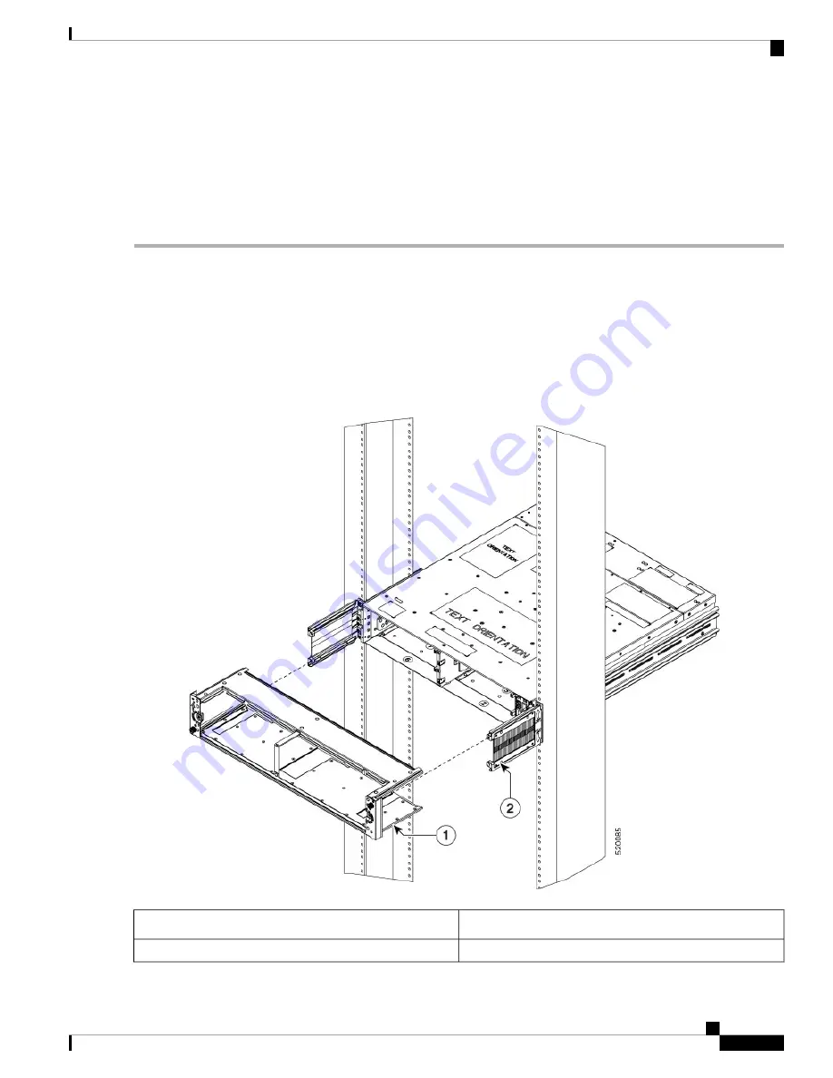
After the chassis is inserted in the rack, fix the air filter side brackets on either side of the chassis. Check for the arrow
indications on the side of the brackets. Using the Philps screws on either side, bind the chassis and the air filter side
brackets to the rack. Tighten the Phillips screws ( 48-101524-01) using a number-2 Phillips screwdriver, to a torque value
of 4.65 N-m.
In case the air filter is being installed after the chassis installation is completed, then unscrew and remove the
four screws (on either side) that bind the chassis to the rack. After fixing the air filter side brackets, only three
screws are used on either side, to bind the chassis and air filter side brackets to the rack.
Figure 50: Installing the Air Filter Frame and Side Brackets
Note
Air Filter Frame
1
Air Filter Side Brackets
2
Hardware Installation Guide for Cisco NCS 1004
53
Install Cisco NCS 1004 Modules
Install Air Filter


